Bancroft

  I am planning to make all of the scenes below 18 inches deep. This will allow just enough room on either side of the right of way to capture the feel of the passing scenery but not force me to do a great deal of additional modeling. This will also allow the modules to be reversible on my home layout. For these rural scenes that become "distance makers" to separate towns, this will be important because I do not know what the final layout configuration will be, or what side they will be viewed from.
 
NEWBERRY RD:
NEWBERRY ROAD BRIDGE
  Newberry Road bridge is located just west of Durand about halfway to the town of Bancroft. This bridge scene will be situated in the middle of a six foot long, 18-inch-deep module. This bridge has seen a lot of repairs through the years from both the City of Durand and the Grand Trunk Western. On many occasions the road has been closed for one reason or another from fire damage to automobile accidents. 
  
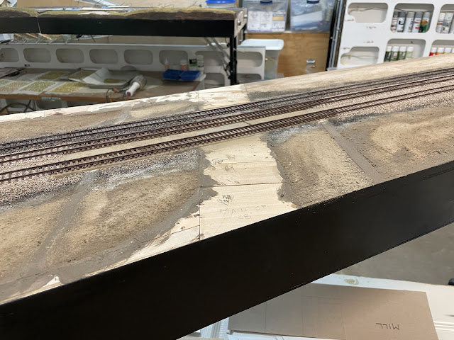
  The Newberry Road module uses my new veneered high side module fascia technique which will save an enormous amount of time for scenes featuring tracks traveling thru a cut. It will also eliminate any visible seam. Here it is below with roadbed and bus wires installed waiting for track.

 
Fascia trimmed to height and contour. Ground Goop being applied.


  This straight section will only be for the bridge itself. I will not include the approaches because I do not know where it will find a final home in the future layout configuration. At this point everything is tentative, and I do not want to get to far ahead of myself thus limiting my options and/or forcing me to redo layout sections.

BANCROFT VILLAGE:

BANCROFT
  Bancroft is little more than passing scenery to the Canadian National nowadays however back in the 80's the Grand Trunk Western still ran double track main through here. There were two spur tracks. On the south side of the mains was a 26-car spur, and on the north side was a 5-car spur. I am not sure how much these spurs were actually utilized and will continue to research it.
 
  Below are some of the completed scenes from Bancroft Village. 
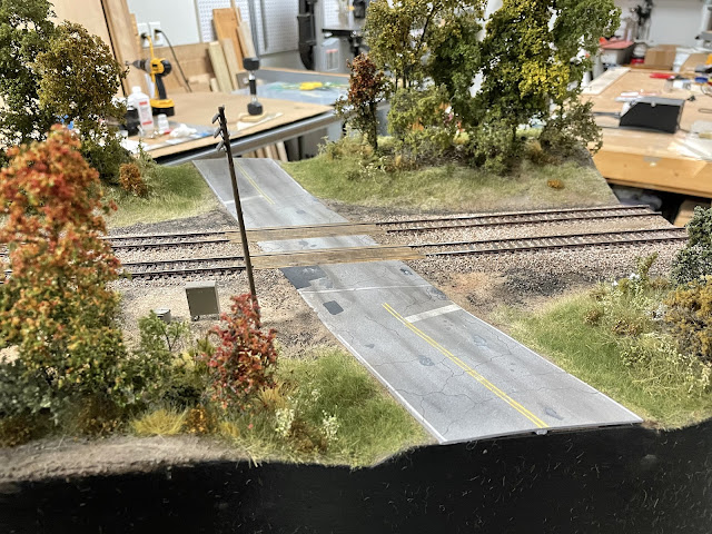
Grand River Rd looking north. No crossing signals in place yet.

Grand River Rd looking south.

Bancroft looking east. Bancroft Truss Company (name unknown) on the left. Norm's Farm Store on the right.

  The Bancroft module sections were laid out first and designed with the new high sides.


  After the foam landforms were in place, the fascia was contoured to match the terrain. Ground Goop was then applied followed by sanded grout.


  Track and rails were then painted.
Primer: Rust-Olium Khaki for mainlines, lighter grays for secondary tracks

My friend Brian Banna assisting with rail painting.

Tamiya XF-10 (Flat Brown) secondary rail, XF-68 (NATO Brown) mainline rail
  
  Followed by tie washes for tie color variation.
My tie washes generally use variations of Burnt Umber and Black artist oils mixed with Odorless Mineral Spirits


  Remaining bare patches were covered with Ground Goop and building footprint templates were added.

Bancroft Truss Company

Norm's Farm Store, Fuel Distributor, and Mill


  Next was sub-roadbed cinder and ballast. Once that had dried thoroughly, the roadbed ballast was applied.


A good look at the tie color variation achieved using this approach. 


My ballast mixes continue to be refined, adjusted, and improved.

The lowly worker bee.

The Supervisor "Why are you taking pictures and not WORKING?!?"

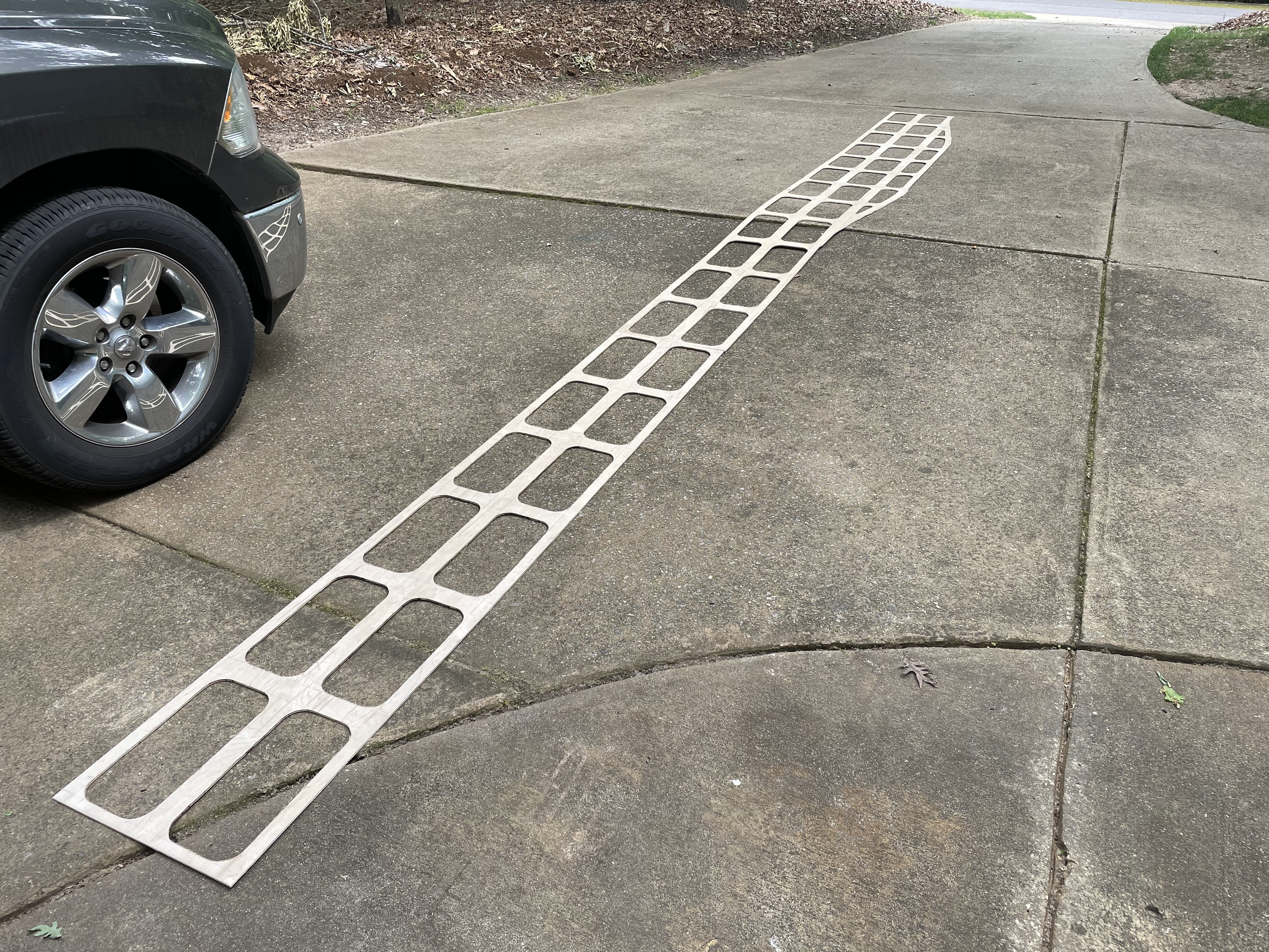
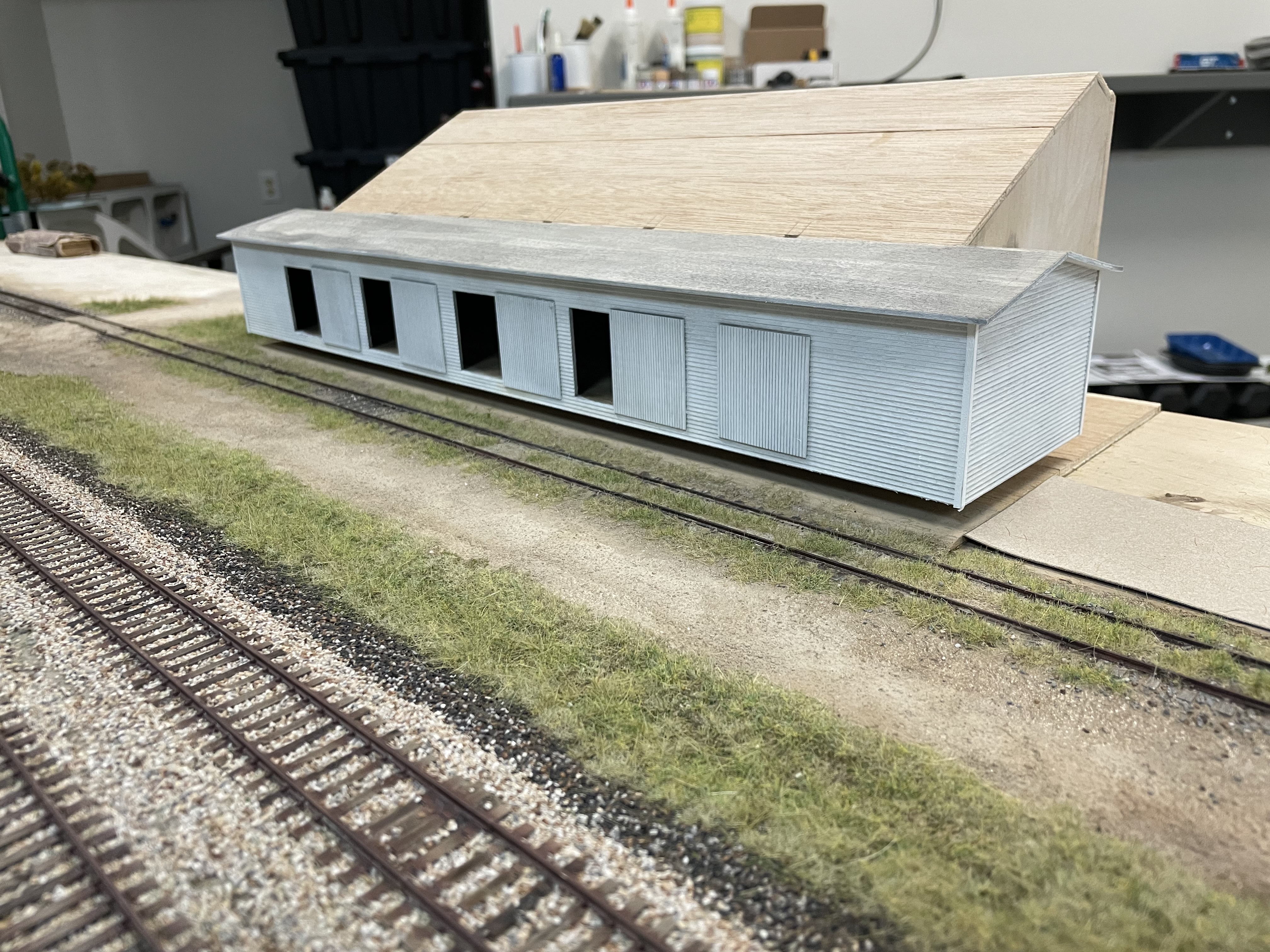
  At this point, I began work on the Bancroft Truss Co. Warehouse. This was built as a 1/4in Luan plywood box core with wood clapboard and styrene sheeting veneered to the outside.

The wood clapboard was stained with wash of IPA and black India Ink

The floor was weathered using PanPastels

The pad for the truss co. warehouse with the truss yard to the right of the spur.

 Back to the module. With all the pads in place for roads and sidewalks, I began working on the styrene street sections. I tend to favor .060 styrene as my medium of choice when building roads.
I try to have a Luan pad anywhere that I intend to glue down roads, sidewalks, buildings, etc...

N. Beach St. was in the process of being removed during this timeframe. 

Broken-up asphalt and potholes. This will be a mini scene of the road being removed.

N. Beach St. with newly built Lake St. to the right. Robinson St. is on the far side of tracks.

Grand River Rd. coming in on the east side of town.
  Static grass and forest floors start to be worked intermittently between various other projects. Even though it is fall, there are still very vibrant greens everywhere. Particularly newly planted grass and areas that are kept up by the municipality.


  More progress on the roads and streets as I got them painted and detailed.
Grand River Rd. painted and graphics

Main St. with Lake St. coming in from the left.

More layers on the forested floor areas.
  The sidewalk sections were completed next. I made these from pieces I dug out of my styrene scrap box. Once I had them built, they were painted solid black. A technique picked up from Boomer Dioramas...thank you Boomer! After that, I used Tamiya Deck Tan to overspray them. This technique allows all of the detail to be seen much more vividly.


Shiawassee St. with sidewalk on the left and Bancroft Truss Co. on the right
  At this point trees and vegetation started to be applied to areas that it was not at risk of being damaged while other projects were worked.  I continue to refine and develop my techniques for creating trees in the early stages of autumn. As my finished products become noticeably better in quality, I know that I will have to revisit some of my previous modules with subtle splashes of these trees in order to homogenize the scenery across the layout.


Small saplings which tend to turn color first.

Lots of homemade grass tufts.


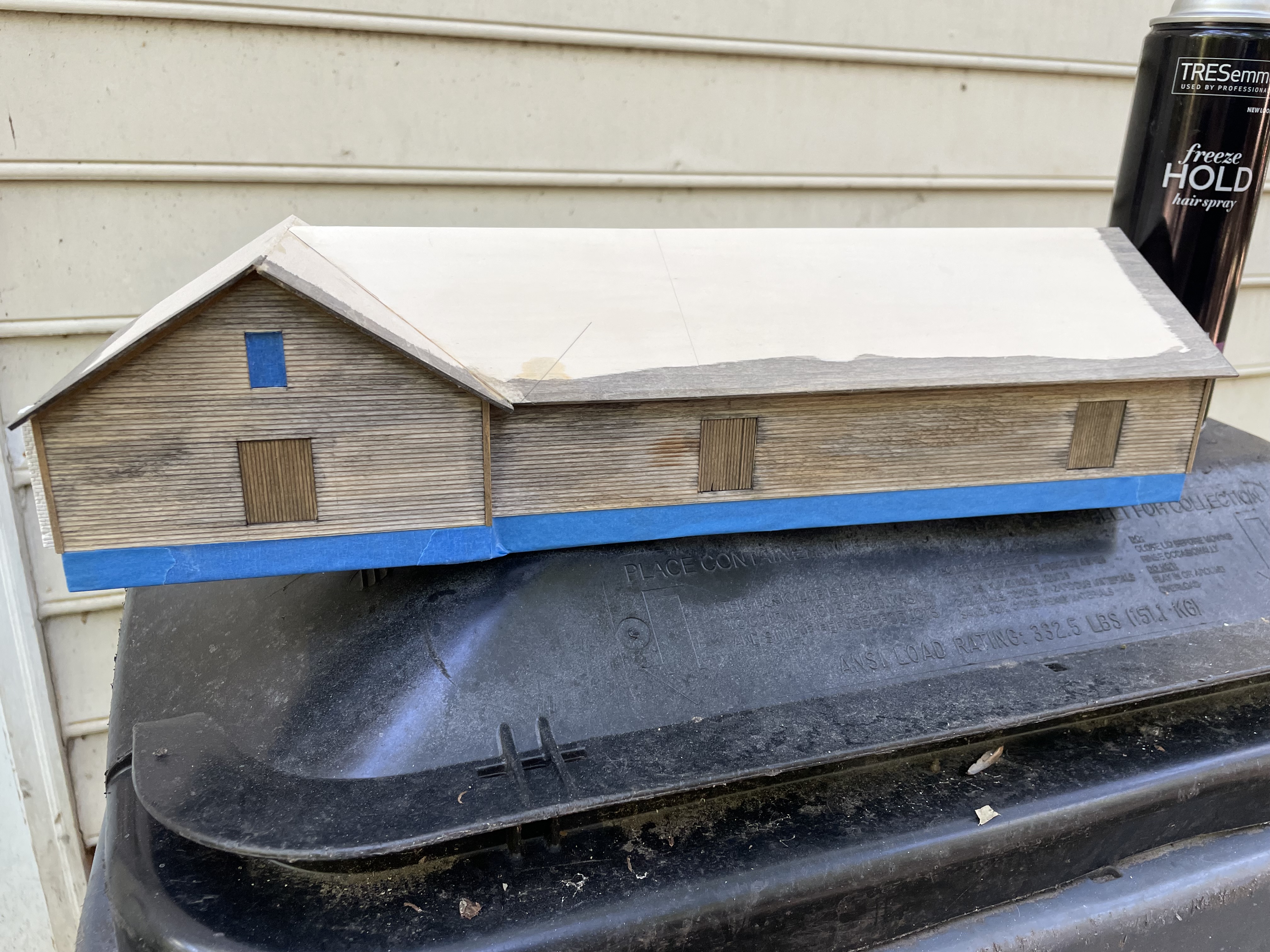
  The truss warehouse was painted white and then chipped to create the look of peeling paint.


Door rail details added

  Norm's Farm Store and Feed Mill was built next using the same techniques as the truss co. I used a little modeler's license here and moved the Purina head house further up toward the peak of the roof so I could capture it entirely. It is very much a signature element of the Bancroft scene.


  I used corrugated sheeting for the roof of Norm's. Rather than cut it into individual pieces like I have done in the past however, this time I tried a new technique in which I simply drew the sheet separation lines on. It is very difficult to tell the difference at a glance and that was fine for me. It saved a bunch of time.
 For the fuel oil distribution tanks, I used those from a Grandt Line kit. I didn't have enough at first, but a friend who had one of the kits sold me his. I had to cut down one of the tanks to get the scene to look true to the prototype. I used wood to create the additional concrete cribs. I then skimmed the wood cribs with wood putty and sanded it to get a concrete-like appearance.

I wanted these tanks to be removable so I could weather them at a future date. To do this I used basswood to create shoes/sleaves that the cribs would seat into. I then embedded these into the scenery base.

 To the west of the feed mill is the old foundation to another part of the building that no longer exists. This area is used for parking these days.
  At this point, I started adding more weathering detail to the streets as well as adding and creating scenic elements to finish out the scene. Power lines, line poles, telephone poles, meter boxes, signal and battery boxes, etc... all lend to make an otherwise bland and flat scene visually interesting.


SHIAWASSEE RIVER:


SHIAWASSEE RIVER (Photo by Steven McKay)
  The Shiawassee River scene will be 18 feet long. The bridge crossing the river will be centered and the scene will be bracketed by Exchange Road on the east end, and Byam Road on the west end.
LOOKING EAST ALONG THE SOUTH SIDE OF BRIDGE

VIEW FROM EXCHANGE ROAD
BYAM ROAD CROSSING
  The river scene has got sub-roadbed glued in place and standing by for roadbed and then track.

Roadbed is in place and the scene is awaiting track. Other than getting legs designed and attached, I am at a stopping point here until I can get some carriers made for storing the modules. Once track is put down, I will no longer be able to stack the modules as is their current state when not being worked on.

  Legs have been attached. This is just a simple folding leg design. I am not putting wheel on the due to stability issues created by the narrow footprint.

  Using up scrap foam to create the raised fill on either side of the Shiawassee River crossing.

  Here is a look at the start of my carriers for the river crossing and Newberry Rd. Carrier construction is beginning to become a critical need in order to allow space for construction. Once a module has track and/or scenery on it, one can no longer stack modules in a corner to get them out of the way.


  Using up more scrap foam to create the raised fill, and getting the Luan fill profile glued to the end plates. The waffle bottom for Durand Yard 2 of 5 is standing against the wall while in the background, waffle bottom 3 of 5 is being cut.
  I am using foil between the Luan fill profile plates to make sure they don't accidentally get glued together. These profile plates will ensure that the scenery flows smoothly across the gap between the two modules, and also prevent the gap from widening as the foam shrinks over time.
   I spent an afternoon getting track installed on the Shiawassee River module. The bridge section will be cut out at a later date during scenery application.

   
 28 April, 2020

  After nearly a year and a half since my move back to North Carolina, I am finally back into working on the railroad.  Production is still slow at this point but moving along none the less.  I started working on the Shiawassee River crossing scene which required a great deal of effort in order to correct an oversight on my module profile in relation to the scenery.  In the huge headache that was the process of essentially redoing the entire module front I came to a realization. I had performed this task before on Trowbridge even though no mistake had been made on that module. Hmmmm??? So then the gears started spinning in the brain housing unit. How can I avoid this time consuming process in the future? The answer that I came up with has lead me to a new design concept for Z-frame and raised fill modules. They will now be constructed with full height sidewalls that can later be trimmed to the desired profile once scenery is determined. See Misc page for pictures of the new standard.

 Aside from redoing the module profile board, I have began work on the actual river crossing.  After removing the bridge track and cutting the temporary roadbed out of the gap, I began by measuring the spans of the bridge and determining abutment locations and wing wall angles. 

  Next I built the mounting sub-structure for the abutments and wing walls out of Luan and 3/4 Plywood. These will eventually get glued in place and allow me to remove the styrene abutment components from the module to work on. In the second picture below you can see my anticipated water line on the right wing wall section.


  The abutments were then constructed out of styrene to seat over the top of the mounting base.  These are foundation on which the rest of the abutments will be formed. 


  The intermediate pier sub-structure was cut from 3/4 in. Oak Plywood in two sections which are then glued back to back.   After this section had dried, the Ice-breaker bevel was cut.  This was actually much more complicated than it initially looks.  The cut is an angle at an angle to get not only the proper wedge dimension, but also the batter (slope from bottom to top) of the overall pier.  Batter according to historical MDOT standards should be around 1:12 for front slope, and 1:6 for back slope. Since the back slope is not visible on a model and therefore unnecessary, I only needed to worry about the front/face side. Without having exact measurements of the pier and abutment heights, I guestimated using all the pictures I had available to me and my bevel.  After doing a mock-up, I selected the slope that was visually closest to the prototype.  After cutting the Ice-breaker I used a wood file to achieve the final contour.  This sections was then glued to a base which brings in to the proper height. The entire assembly was then covered with two coats of varnish to prevent any warping from water, atmosphere, glue, etc...This sub-structure will get two layers of .060 sheet styrene veneered to it which have been calculated into the final dimensions.

Varnished intermediate pier ready for styrene.

  For this bridge I will be using two Micro Engineering 85' Open Deck Girder Bridge kits. This gives me four girder sections to form the outside visible portions of the bridge.  The inside sections will not be visible to the point of being able to see details even with the open deck. I will therefore construct the inside girder sections from .060 styrene. 
Test fitting the girder spans in the gap.
  The profile board now complete, I can now push forward with this scene. Here is one last look at the entire module before the first major scenic transformation. 

  And here the ground goop (see MISC tab) has been applied to cover all the land forms.

 For the base coat of primer on the track of this module, I am experimenting with a new color. Rust-oleum Camouflage, Khaki #279177


Here it is applied to the track.


  With the first of two layers of .060 styrene veneered to the intermediate pier, I did a test fit in place and centered everything up before gluing a bracket down that the pier will seat into. Like the abutments, this will allow me to remove it and continue to work on it while completing work on the riverbed. 


   Once the bracket was dry, I began applying the remaining ground goop to the abutment and riverbed area. 

  The second layer of .060 styrene brings the intermediate pier to its final dimensions. I then added the footing and began the spalling process.
First pass with spalling


  I worked from photos to try and create the desired pattern.  I worked in layers, first drawing the pattern onto the styrene with a pencil, then using X-acto knives, files, and Dremel tool to form the relief.
The pattern of spalling and cracking drawn on with pencil.


  Next I started on the first abutment follow the same process using photos for guidance to match the prototype.  These abutments and wing walls have an incredible amount of detail and character that make them interesting to look at.

  After assessing my original plan to build the inside girders out of .060 styrene, I determined that I could get a much more rigid structure if I reinforced the girder.  I wanted something lightweight that would keep everything in alignment while providing the additional support I was after.  What I came up with was 1 1/8 inch aluminum yard sticks.  I cut them both to length and then veneered the .060 styrene to them using E6000 All Purpose Adhesive.
  Below are my components organized prior to construction.
  One thing of note, in going with this technique I was required to build additional components for the bridge.  Splitting the bridge saved on cost, but left me with only half of the structural components.  Building my own bracing was not that big a deal though, and actually strengthened the design.  Ultimately, even as a open deck bridge, the tie spacing and additional details of the prototype will limit visibility of the inside of the bridge to the point of irrelevance.  
  Once the web of the two girders were cut to length, I did one last test fit to ensure they would fit as intended.
Ensuring the new girders matched the length of the kit girders.
   Once I was satisfied that all of my dimensions were correct, I began assembly of the bridges.  I periodically checked my progress by inserting the bridge into the gap checking for squareness, alignment, etc...I will install the elevation pedestals at the end to bring both bridges up to the final height.


  Several sections of the cross bracing for the second span needed to be scratch built.  After fabricating one of these bracing components, I confirmed my suspicion that they will be very difficult to see in any detail thru the bridge crossties.  With that in mind I proceeded to build these sections a little more robust than the Micro Engineering kit components.
Additional cross bracing sections being constructed.
    The second span was completed and test fitted in the gap.  Before I add the elevation pedestals, I will be finalizing my plan for the deck which will be scratch built with a combination of PC board ties, 3/32 x 3/32 basswood, and various structural components. I had originally intended to use brass, but after the Special Shapes Co. was absorbed by K&S, many of the smaller brass stock items were discontinued.  The alternative I am prepared to go with is ABS plastic components.


   The bridge tracks for this particular scene have no guard rails.


   The two grade crossings on the module, Exchange Road on the east end, and Byam Road on the west end are wood planked as seen in photos above.  I do not have any photos of what they looked like in the 80's.  Since then they have been upgraded with the prefab pressure treated hardwood grade crossing panels.  Knowing that these were most definitely hardwood planking typical of that timeframe, and knowing that I would have a number of these types of grade crossings, I decided to order some laser cut inserts to save time.  I ordered Blair Line and GLC products. Walthers and Woodland Scenics were out of stock from my supplier.  I have made these in the past using scale lumber and gluing individual planks to a piece of styrene that was then glued down to the ties.  When these products arrived, I was somewhat disappointed.  I have many photos of oak plank grade crossings.  The Woodland Scenics version has 4 planks.  Both Blair Line and GLC have 7 planks.  I have never seen a single photograph of a prototype grade crossing showing any of these board counts.  I have seen the number of planks vary from 2, 3, 5 or 6 and even 8 in one case. NEVER 4, and NEVER 7.  Why this is important is to do angled crossing where the boards are offset, an even number can be split into sections of 2 or 3 and it looks prototypically correct...because it is.  The only one I did not get my hands on was the Walthers kit, but from the pictures I have scene, they may have gotten the board count right. 
  Also of note, The Blair Line product requires the modeler to notch the underside of the planking to fit over the track spikes.  GLC provides a separate piece that glues between the spikes to avoid this headache.  The modelers preference will dictate.  Here is a look at the two products.

GLC grade crossing on top, Blair Line on the bottom.
GLC on the left, Blair Line on the right.

  Regardless, I opted to make my own for this module. To do this I am using Northeastern Scale Lumber 3/32" scribed sheets.  Disregard the price on this package as it may be two decades old.

  The sheets are cut to length to allow for a 22' improved dirt road.  Below you can see the 3 board offset to compensate for the angle.
Exchange Rd.

  At this point I continued to refine the terrain for the desired features. On the west side of each of the grade crossings, the railroad had to build up the bank of the fill and create a service area to allow signal cabinets and associated hardware.  At the Exchange Rd location, the fill was rather steep, so riprap was used to prevent erosion issues.  I used some old play sand to create a lip for the riprap. I wasn't concerned with the orangish color of the sand as it was painted after the glue dried prior to being covered with sanded grout to blend it in with the platform directly above.  I had also tinkered here with some sub-roadbed ballast colors and static grass to determine if the colors were going to be suitable. In the case of the ballast, the answer was no.
Creating signal hardware service area along Exchange Rd

  On the Byam Rd crossing, I further refined my ballast layer colors.  Here the railroad used steel bulkhead panels to create the service platform.  I would later scratchbuild these out of styrene.  In the below photo, I have the darker sub-roadbed ballast with newer roadbed ballast on top.  As stated elsewhere, for my ballast I use a mix of Woodland Scenic ballast to create the desired color blend. I would later refine this again as my mixes changed.  For the most part however, this scene was close enough that I didn't need to make to much adjustment.  For the roads I am using sanded grout mixes.  You can also see the initial ground cover layers here.  I like to use fine turf for the lowest layer, representing moss and smaller leafy weeds.  Where wooded areas will be, I used ground leaves as the start of the forest floor.

Byam Rd

  Next is the first layer of 2mm static grass. Like ballasting, I like to use a mix of colors in my static grass rather than applying individual colors.  In my opinion, this renders a much more realistic appearance.  I keep track of all of my mixes using an Excel spreadsheet so that I can reproduce them on future modules.
Woodland Scenics Talus used to represent riprap at Exchange Rd.

  The next layer is 4-7mm static grass. 


  For the wooded and high vegetation areas, the next few layers represent the composting effect of nature. Various applications of fine turf, more dried leaves, followed by course turf, clump foliage, sticks and debris all combine to give the desired look of forest floor.


  This was followed by the next layer of tall static grass where I begin working on the patches, tufts, and clusters of dead grass and weeds.  I try to achieve the general look I see from photos of the area taken during the desired time period.  I don't concern myself with the names of each species of weed or grass, but rather I focus on capturing the essence.

 
After t
his I continue with more low-lying leafy vegetation, small bushes, etc... I use a variety of different products for this ranging from simple course turf, clump foliage, and poly fiber shrubs to store bought bushes I find that suit my needs.

 
Once all the low vegetation was completed, I started working on the wooded areas beginning with the wood lines.  In most cases, the wood line is where the foliage is the densest due to the amount of sunlight exposure.  I prefer to work these areas from both sides in order to pack in as much vegetation as I can.  I also like to incorporate larger tree trunks using branch material collected out of the yard from various plants and shrubs.  The SuperTree material is great for smaller trees but does not have the stem thickness to represent mature deciduous trees. In addition, adding additional trunks that can be observed thru the tree line makes the scene look more realistic. The tops of these will be covered up within the canopy of adjacent trees.


  As I work backward toward the edge of the module, I start to thin out the vegetation about 20 ft into the wood line where there is less sunlight.
Working backward toward the edge of the module.

  Little splashes of "Different" can bring life and interest to an otherwise bland forested scene.  I try to add as many visually interesting areas as I can to my wooded areas, otherwise it just becomes "More of the same" when looking at long stretches.  In some cases, this may be what I want, but generally speaking I like to pay particular attention to areas within 12-18 inches of a grade crossing, or a signal or anyplace that may serve as a natural focal point for photography.  
Byam Rd

A patch of dead and dying timber to break up the wood line.

Exchange Rd

  At this point I decided to start the coloring process for the intermediate bridge pier.  This is a multi-step layering process using washes, chalks, weathering powder, and colored pencils to slowly build up to the desired look.  Because I was experimenting with colors, I did not take pictures throughout the process, but I did annotate every step on my color sheet.  I will go over the layering process in detail along with pictures of the process when I cover the abutments.  Overall, I was very pleased with the results.
Intermediate bridge pier

  As the fill gets deeper into the river basin, and close to the bridge, retaining walls are needed to keep ballast and roadbed intact. Gravity plays its role and is very evident as dirt, cinder, and ballast are pulled down the slope by Mother Nature as she does her thing.

 The layering process continued as static grass and ground cover was added to the fill slopes near the bridge.
2mm dead static grass followed by 2mm live
4-7mm mixed fall blend
Second layer of 7mm for taller patches of grass

Leafy weed foliage and low bushes added


  For the river itself, I decided to go with MAS Deep Pour Resin which is a two-part epoxy resin that comes highly recommended by artists who work with resins professionally.

  In order to experiment with ink and bottom detail colors to determine my final mix, I build a test pour box divided into 4 chambers.  I created varying bottom contour and color detail in each chamber.

  Next, I used prototype images to select bottom tint colors which I applied as washes and sprays.

 
I then added and recorded different measurements of Espresso Alcohol Ink dye to small portions of resin and did individual pours in each of the first three chambers.  The fourth chamber was kept in reserve to do a final pour based on the results of elements from the first three.  The test pour box was then set aside to fully cure.

  Back to the bridge, utilizing prototype images as inspiration, I completed the coloring process for the first of the two abutments.  Again, this process will be covered on the final abutment.
East abutment styrene base final cracking and spalling

Primer coat added. This is Rust-oleum satin Smokey Beige

Multiple layers of weathering powder, colored pencils, etc...

East abutment test fit in place

  Transitioning back to the Byam Rd grade crossing, I roughed up the timbers before staining them a darker color.  Here I took into account the right-hand running practice of the GTW on double track mainline.  The lead edges of the timbers were gouged and chipped to reflect years of damage from passing trains.

  Next, I used an airbrush to add a layer of dust and pulverized sand to the surface of Byam Rd as well as the crossing timbers.

  And then, onward to the main event!!

  After much time to deliberate over how I wanted to tackle the Shiawassee River itself, I finally set forth.  I started with rechecking my initial calculations for the path of both riverbanks.  Getting this as accurate as possible was important to help in calculation of resin volume that would be required.  I also began drawing in the footprint of sandbars and river bottom detail.

NOTE:  When preparing your surface for a resin pour, particularly deep pour resin which has a longer curing time, you must have all insulation foam, Styrofoam, etc... covered with at least 1/16 inch of hard-shell material.  The resin will melt the foam with the off gasses will create bubbles in the resin which cannot be removed. 


  Next, I used additional ground goop to form the sandbars and further enhance the riverbank detail.


  These areas were then covered with more sanded grout.


  Once everything had dried, I went over the sandbars again with a lighter sanded grout.

  Once the sandbars had sufficiently dried, I went over the river bottom with my predetermined wash to pool into the deeper areas followed by an overspray with the airbrush.


  Riverstone was then added to the area on the west side of the pier. Once it was glued in place, I went back over it with more sanded grout to give the stones the appearance of being embedded in the river bottom.
 

  Logs made from shrub branches were added to the riverbed along tree roots created using grass roots from my yard.

Grass roots were used to represent tree roots

  More layers of smaller branches and debris were slowly added.
  
  Next the pier was put back in place and I started adding logs and fallen trees that would extend above the water surface.


  These logs were glued in place, and then I painted them and gave them a series of washes to give them the sun and water bleached look.


  Again, even more debris was added where it would naturally accumulate under the log jams.  The pier, abutments, and bridge were then put back in place to get a look at the final scene composition.


  I then created a cover that would keep dust off the resin during its curing time.

   To prepare the scene for the resin pour, I removed the abutments to avoid getting resin on them unnecessarily. I then taped off the front and back edges of the module using blue painter's tape. The tape was then sealed along the edges to prevent resin from leaking. This was followed by clamping boards to the outside of the fascia to prevent the resin from bowing out the tape.


  Finally, I used my previous calculations to mix the appropriate volume of resin.  I then used the alcohol ink mix that I determined from my test pours to color the resin.  At this point I wondered if all modelers and artists getting ready to make a resin pour went thru the same gantlet of emotion given the amount of prep time that had been gone into the project to this point.
 
  Starting in the middle of the riverbed well away from the intermediate pier, I began slowly pouring the resin.  The slow pour minimizes bubbles as much as possible however it is inevitable that there will be some.  These are easily removed after the pour is complete. You can use a small torch to quickly pass heat over the bubbles or blow thru a straw onto them. Either the heat or the carbon dioxide will pop the bubbles. Let gravity do its work and allow the resin to self level. PATIENCE is a must at this point. Don't worry about rushing as deep pour resins take upward of 24-48 hours to cure. I used the intermediate pier as my gauge for desired depth.


  If at all possible, try to keep any scenery material away from the riverbank. This will minimize the desire for the resin to "creep" up the bank in a wicking effect. It is expected that there will always be some creeping however.
The resin will wick into anything it comes in contact with.


  To fix the appearance of this wicking effect, I essentially redid the scenery that had been affected. I first used ModPodge gloss to mask off the river resin in order to protect it. Next, I reglued sanded grout to the riverbank. Once the grout had completely dried, I pealed back the ModPodge layer leaving me with a clean line along the edge of the river.


  After one last test fit, it was time to glue the abutments in place. I used reversed clamps to ensure they didn't move while the glue was drying.

  Placement of bushes and trees along the riverbanks came next. In this case, the area with resin creep was covered up thus working in my favor.
 

  With the help of my good friend Brian Banna, who had his paint shop permanently set up at the time, I was able to get the weathering complete on the bridges. Both received a heavy application of fading and rusting. I really do miss that purple therapy pig that Brian kept handy!

  The bridges were then test fitted into the gap again and I marked and measured the location and height of the bridge bearings on the intermediate pier.


  The bridges are designed to be removable if necessary. They are held in place by screws into the abutments. This styrene screw block was painted black before final installation.

  I added the tie guard rails for both sections of bridge track. I used fine sewing pin heads to represent the bolts. They are slightly overscale, but noticeably so once painted. The bridge tracks were then placed their respective bridges.


More low vegetation and bushes added to the wing walls and riverbanks.

  From here I continued to fill in vegetation along the wing walls, riverbanks, and sides of the fill.


  Little details were then added to the scene. Powerlines, RR line poles, street signs, the mailbox visible along Exchange Rd, etc... all add to the overall scene in subtle ways.


Still left to do:
  At this point the scene is around 90% complete. I still have bridge handrails to be built, crossing signals which will be added at a later date, and river current detail to be applied to the water surface.


S. STATE RD: 

  Nothing spectacular here by way of interesting scenery. State Rd is more or less passing countryside to the operator. It does give placement however and adds to the interest of the mainline run.
S. State Rd looking south.
 
  For State Rd I used the module originally intended for Newberry Rd.  Like Shaftsburg Rd, it is currently being utilized in my attic. The scenery is completed to the same degree.
Partially completed scenery.


COMPLETED BANCROFT SCENES:

  Although I had been unable to update the blog for quite some time, work has progressed on the layout. The following are some pictures and videos taken of the mostly completed scenes on the modules. 

 The Shiawassee River crossing on display with the NC Sipping and Switching Society in Raleigh, NC.


No comments:

Post a Comment