
"The
Railroad Town" Durand, also known as the crossroads for the Grand Trunk
Western, is located at the Junction of the Flint Subdivision with the
Holly Subdivision.
 |
| Durand Union Station |
Durand
will be a major focal point on the layout both visually and
operationally. It is therefore being modeled full scale with the
exception of the High Wye which is being slightly reduced in radius.
Some
modelers license is being applied. Although I model the 1980-1990 time
period, the model will depict the station in its restored state. The
station platform will represent the post 1985 condition resulting from
the diamond wreck. |
| DURAND TERMINAL MAP From 1971 GTW Car Control Manual |


 |
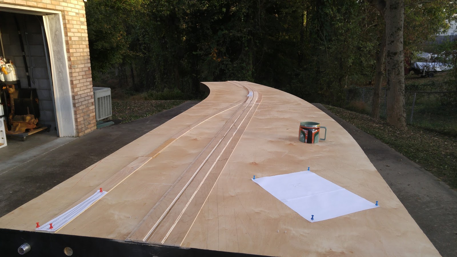
| The west approach on the new Durand Station module. |
This is the station module with all wing sections attached. It measures 16 feet long along the Flint Sub axis, and 12 feet along the Holly Sub axis. Once the High Wye is attached, it will add an additional 8 feet along both Subdivisions.

 |
| Durand Diamonds |
STATION CONSTRUCTION:
This is a model I have been working on which will be one
of the focal points on my future layout.
These first two pictures are an overall view of the building as it stood last year.
I know it is a little out of order, but I first began work on the structure
itself, minus the base. It has been kept sectional, which made it much easier to
move around.


The picture on the wall is out of the book "Evening before the
Diesel". I had it enlarged to HO scale. It is primarily a point of quick
reference however. I use the actual elevation blue prints, and detailed
measurements that I have taken through the years to ensure that this is a scale
representation. I have spent many, many hours in my younger years climbing all
over this building with a tape measure and notepad.
For the stonework, I created a master and then a mold using RTV rubber. I then casted straight sections with Alumilite
It is tapered from top to bottom, so I started with a piece of .060 styrene and then start building up layers using scale styrene strips that were the right dimensions. The final layer is two scale inches shallower as it climbs block courses. The final layer of each course also has been files for individual block length and rounded edges and detail, etc...
The front turrets were done in a similar fashion except the base was a piece of PVC of the appropriate dimension. With this I was more concerned with the inner dimensions of the tube because I was modeling full interior. Again I made an RTV rubber mold and then cast the turret bases with Alumilite.
It was then a process of cutting and fitting. The final step will be to apply modelers putty onto the appropriate stones at the seams so they will not be visible.
One of the more difficult projects was building the lower roof around the front turrets. I built a frame using 1/8 inch square brass tubing with piano wire routed through the core. Using a resistance soldering iron, I flowed solder into the ends to secure the wire in place. I then began the bending process. The finished frame is very rigid.


Here are some of the prepared lower roof sections.

Here is the rear lower roof section


Here are a few photos showing the layout of the interior.
1st Floor

The ceiling of the 1st Floor is made of etched circuit board which enables me
to remove it and replace LED lights without risk of damage to the model.

2nd Floor

Here are some photos of work completed on the concrete
platform. I have to apologize for the poor quality of some of the photos. These
were taken with my current camera which was not functioning properly.
Also disregard the three tracks in front as they are part of a filler module which is serving as my work platform.
Once the main platform was complete, I was ready for weathering. I experimented with weathering powders on test sheets until I was satisfied with the color.
Also disregard the three tracks in front as they are part of a filler module which is serving as my work platform.
Once the main platform was complete, I was ready for weathering. I experimented with weathering powders on test sheets until I was satisfied with the color.

Here is the damaged concrete sections prior to painting.


And after the base color was applied.

Continuing with work on the concrete. I worked on the crumbling original concrete
platform. It is only visible on the Holly Sub side (long axis of the depot).
After the new platform was poured, you could only see the old platform between
the fence and the track.
The old platform has been patched many times over as the Michigan winters have taken their toll on it. It has a layered appearance which made for a fun project.
Here I started with grinding away appropriate areas (based off photographs) with a dremel tool, blades, and files.
You can also see one of my color test sheets which I used to try and match the various shades of concrete layering.

The platform closer to the rear of the depot gets progressively worse.

Some additional grinding was necessary as new pictures showed up from home.
Once that was complete, I taped off the area to begin the weathering.
 The first layer was done with weathering powder.

 Next was a wash of Water Mixable Oils to give some depth.

 I then began adding the layers of patch work.


 Here is a photo of the actual platform for an idea of the look I am going for.
 Next I went over it with a wash of water mixable oils to get some color
variation. After that had dried, I used weathering powder to help blend the
colors and make the cracks more visible. I then sealed with dullcote.
Next I went over it with a wash of water mixable oils to get some color
variation. After that had dried, I used weathering powder to help blend the
colors and make the cracks more visible. I then sealed with dullcote.
 I mixed a batch of raw umber water mixable oil thinned with microsol, and using
a fine brush, ran it into all the cracks and crevices to give them more
pronunciation. After this dried, I sifted fine dirt (from the actual location)
into the appropriate areas and then glue down with woodland scenics cement.
While it was wet, I sprinkled on fine ballast.
I mixed a batch of raw umber water mixable oil thinned with microsol, and using
a fine brush, ran it into all the cracks and crevices to give them more
pronunciation. After this dried, I sifted fine dirt (from the actual location)
into the appropriate areas and then glue down with woodland scenics cement.
While it was wet, I sprinkled on fine ballast.
 The entire platform is made from laminating sheets of styrene together for
strength. This also allowed me to create a pocket which the building itself
sits in. This locks it in place, and ensures alignment. The top layer is .010
styrene with lines scribed using the back of an Exacto blade along a steel
ruler.
The entire platform is made from laminating sheets of styrene together for
strength. This also allowed me to create a pocket which the building itself
sits in. This locks it in place, and ensures alignment. The top layer is .010
styrene with lines scribed using the back of an Exacto blade along a steel
ruler.
I used a Dremel tool and the smallest bur tip bit that I have to grind out and texture areas that had deteriorated.
On separate scrap sheets of .010 and .005 styrene, I painted various shades of concrete and then weathered them with assorted powders before sealing them with dullcote. I then went to work with scissors cutting out appropriate sizes and shapes for the different layers.
After these were glued in place, I went over with a light wash of water mixable oils to give some additional depth and color variation. After everything was dry, I also went back and highlighted using colored pencils.
Starting work on the main platform. The first shot is the base coat, which consists of a solid coat of Model Master FS 36622 Camouflage Gray followed by an overspray of Polly Scale 585394 U.S. Tac Lt Gray. The overspray is applied so as to allow the undercoat to show through slightly.


The first shot is the stairwell, which was actually finished a while back. I will try to get better photos once I get a better camera. There was a slight ripple in the trim that the camera picked out. I have since went back and corrected the issue.


I then used colored pencils to draw in the veins using pictures as a guide. Once I had them the way I liked, I sealed them in with Krylon Gloss Coat Acrylic.
The next pictures show the experimentation with photo color and sizes of the interior floor.


NEW MODULE BUILD:
Durand Union Station will be moving to a new home.
A new module is under construction that will be the home of the Durand Station. The previous platform that I built on was far to heavy and still showing signs of warping. The new box, also built to S&SS standards, is 3 feet longer and will allow for a far more photogenic scene.
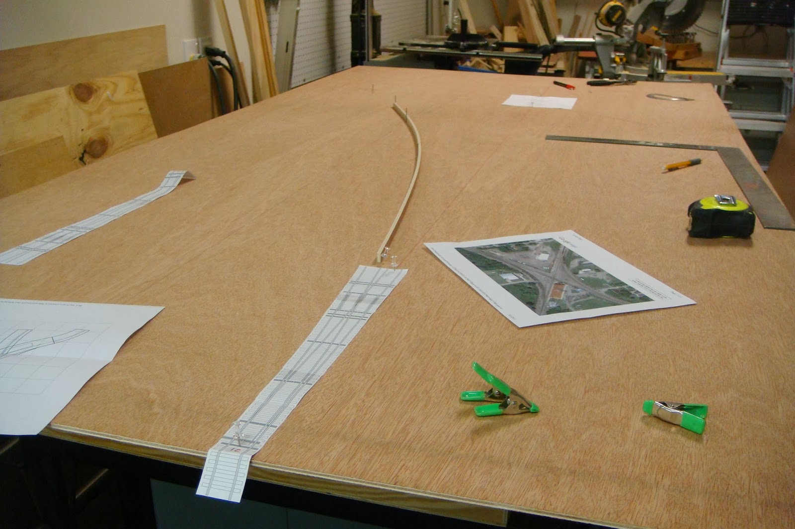
The first photo shows the designing of the module. The turnouts leading into the Wyes will be hand laid number 12's. This combined with the long easements into the spiral curve should be sufficient enough to handle the longer trains. On the prototype, this was a slow down curve anyway.


Here is an overall look at the module with all wing sections attached.


Here the process of swapping to the new base begins. The new base will not have tracks mounted to it.


DURAND DIAMONDS:
I started the build by first drawing the crossing onto the base and then drawing out the diamonds to scale on a piece of paper.


Instead of styrene, I opted to use the same technique I used in my Owosso diamonds for shaping the frogs and filling gaps. I am using Loctite Liquid Weld as the filler. It's a two part resin which bonds everything together nicely. I made a simple styrene form to get the desired shape. I coat it with petroleum jelly to keep the resin from sticking to it. Once it hardens, I remove the form and start on the next area. After letting it dry for a day or two, I filed the hardened resin flush with the rail tops, and went to work with Exacto knives clearing all unwanted material.


Here the flange ways are cleared.
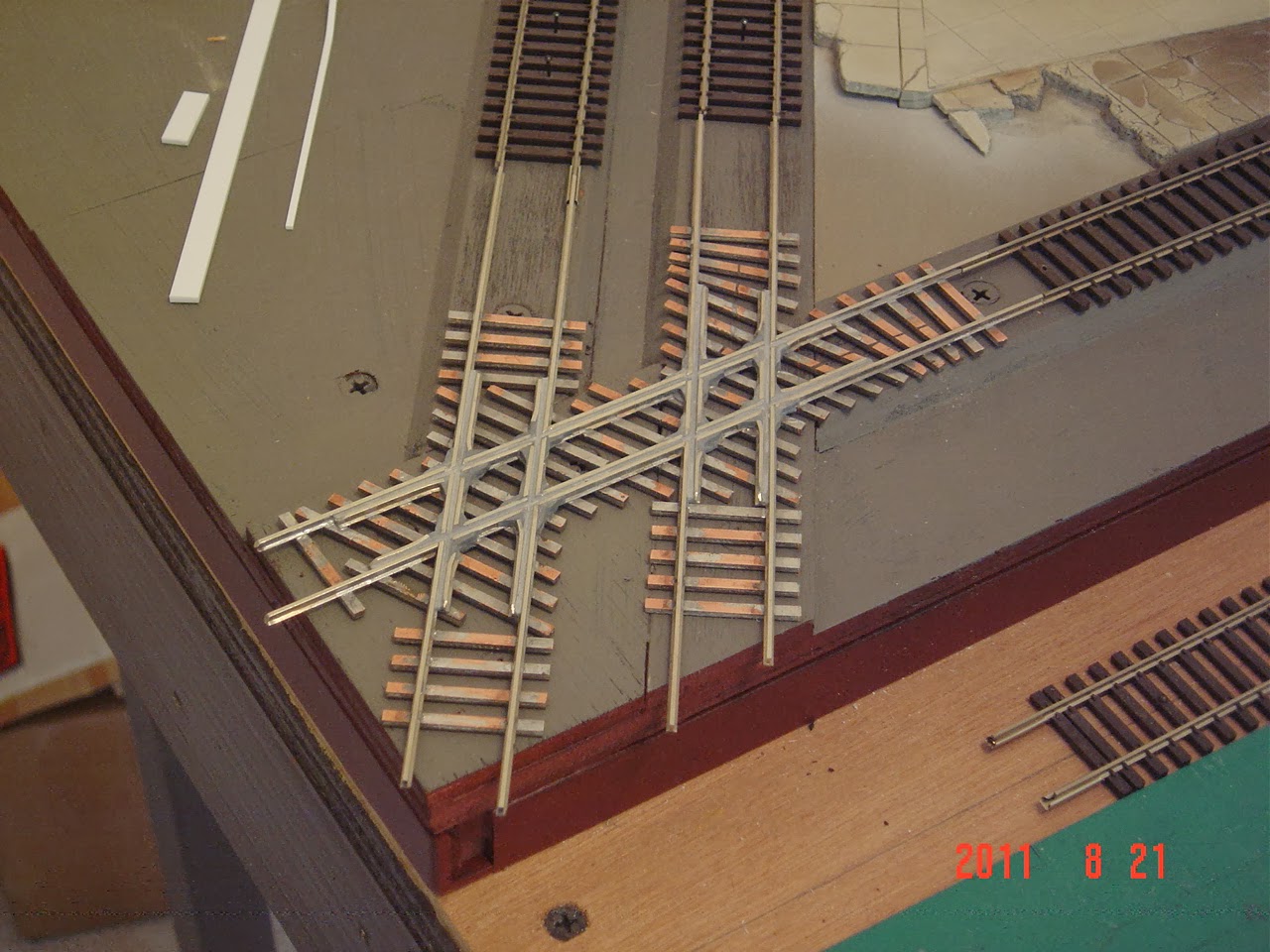
Here, all gaps are cut and filled with pieces of .005 styrene. It is now ready to start the detailing process.


The fish plates installed. I still need to do minor fills, putty and sand all the gaps at this point, and then on to installing all of the bolt details.

Here the tie plates are installed and I have filled the electrical gaps.

The diamonds are built to NMRA standard. The flangeway
gauge clears. The flangeway tool that I have/use leaves a slightly concave
bottom. When viewed from the side, it looks shallower than it really is. I am
going back and trying to clear some of the extra material out of the webbing on
the inside of the rail. Other than that it works fairly well.
Unfortunately, it leaves a slightly wider than prototypical gap between the rail and the guard rail. I originally thought about making the gap narrower (maybe proto 87 standard), but I don't want to shoot myself in the foot. This will be the centerpiece for my layout. I am also constructing an adapter base that will allow me to plug into other modular layouts if desired. That said, I want the trackwork to accommodate ALL rolling stock.
Unfortunately, it leaves a slightly wider than prototypical gap between the rail and the guard rail. I originally thought about making the gap narrower (maybe proto 87 standard), but I don't want to shoot myself in the foot. This will be the centerpiece for my layout. I am also constructing an adapter base that will allow me to plug into other modular layouts if desired. That said, I want the trackwork to accommodate ALL rolling stock.
I ended up having to order another package of bolts. Out of the 200 bolts that come in the package, I may have lost 4 (which is actually pretty good considering the way they were flying all over the place). Overall, the project took approximately 250 bolts.

All bolt details are finished. Here is the primer coat. It is Testors 1233 Flat Light Aircraft Gray.

After the primer dried, I started with the washes.
The first was Burnt Umber Oil thinned with Mineral Spirits. The consistency should be slightly thicker than coffee. When this wash is applied, it breaks down the primer coat slightly and blends the two colors together well. One thing I observed is that this process normally brings out the wood grain detail on regular flextrack. Here however, it tends to pool a little more on the PC ties. I was not concerned though as there are follow on washes.

After the first wash has dried overnight, I applied the second wash.
To achieve more color variation and depth I applied a second wash of Raw Umber Oil thinned with Microsol. This wash also allows a little more control of the final outcome as it is erasable the same as if working a freight car. Some areas on the sides of the ties did not accept the washes well, but these areas will be below the ballast line.

Here I have masked off the ties, and applied an airbrushed coat of Floquil Rail Brown to the rails. The leads from the frogs will go to a Hex Frog Juicer which will be mounted under the base.


With another one of these crappy sunny and 70 degree February days, I decided to take everything outside and get some good ole vitamin D while I worked on getting the Durand diamonds in place. This project has been long overdue, and needed in order to connect Durand Yard to a Sipping & Switching layout.

More work completed on the station module today. I am working from the diamonds out toward the edges.


ZONE E:


So there I am with my plan in place to build track work on the Durand station module as it existed in 1985. All of my photos support this track arrangement, so I am comfortable to push forward with this plan. Then along comes this incredible photo by Charlie Whipp from 1982 (still in my timeline window) of the track work and switch lamp locations along the Flint sub as it passes the station. Coincidentally, I have not physically laid this track yet....hmmmm......a change in the plan says I. This photo will allow me to capture the track work accurately in a way that none of my archived photos do. Operationally this was a big advantage for yard crews as it allowed them to move pick ups and set outs from the double siding just west of this photograph without fouling the mainline.
 |
| Durand 1982. Photo by Charlie Whipp |


 | |
| OAK STREET CROSSING 1991 with Simplicity in the background. Photo by Jack Smith |
ZONE M&R:


DURAND YARD:
Modeled full scale, Durand Yard would be nearly 70 feet long. I am going to attempt to model it as faithfully as possible in only 40 feet.
The yard itself is essentially comprised of three double ended switching areas. A Center Track extends straight down the middle of the yard. To the north of the Center Track is North Yard running the entire length. The southern portion is split between South and West Yard.
Originally I planned on using 42 inch wide modules to capture the main portion of the yard. This would allow me to model everything up to the RIP track. Unfortunately it would not be able to get the old coal tower and engine service tracks into the modeled area. After further consideration, and consulting a friend, I have opted for a 48 inch wide module in order to incorporate some of the key signature elements of the yard. With that being the case, all that will be missing is the old roundhouse location and associated service tracks. These would primarily be scenery if I did have them so I hope that possibly a scenic backdrop may be sufficient in capturing the flavor.
 |
| 1984 Aerial photograph taken by Jack Smith |


Cutting out the waffles can be one of the most enjoyable aspects of module construction (insert meme of face vomiting here). This particular one took a little creative head scratching. In addition to rounding the curve, it transitions from 30 inches wide on the depot end to around 43 inches as it approaches the yard where the modules will ultimately be 48 inches wide.


More waffles cut while waiting for glue to dry on the curve. Unfortunately the current space I am working in does not allow me to glue together more than one module at a time. Only four more waffles to cut now for the yard.


Gluing the top down on the curve.


The first of five yard sections is complete. All sections are being painted in preparation for track.


Prior to gluing the last end plate on Durand Yard section five, I was able to get everything set up outside in order to get accurate measurements. As it turns out, table number five will need to be shortened by 1/4 inch to keep the final length at exactly forty feet. If this were just a home layout, this would not be such a critical aspect, but this module set is also intended to be able to plug into S&SS layouts. This means it must stay within the layout grid.
The first two pics show yard tables one thru three with the yard throat attached. In the background is table four being sanded and checked for final square. Table five is being glued up on the work bench.


The next pic shows yard tables one thru four. Unfortunately my driveway is neither long enough or flat enough to get all of the table set up together.

Durand Yard tables are complete. I was able to get everything outside today for mock up. All five tables measure out to 40 feet on the nose. In order to fit all five tables in my driveway, it is necessary to prop the table legs on the downward side of the slope.


More of the yard throat drawn out on the tables today. I made a footprint template for the Grocery House and got that positioned along with a template for the coaling tower. The tracks on the right are the old covered loading dock tracks which were used to store much of the MOW equipment during the time frame I model. The tracks running off the front right corner are the leads to the engine service facility.


Table edges have been painted, and the process of installing alignment pins has begun. For these four foot wide tables, I am starting from what I have picked to be the front / control edge and am walking the template back. To do this I am drilling the first four holes, then using two temporary pins to align the template to drill the last two holes.


Cutting and installing all of the bus wires and connectors prior to installing any roadbed and track.


Gluing down the roadbed for North Track. Getting the track elevation determined and laid out is tedious and time consuming, but will make a huge difference in terms of authenticity of the scene. This will be particularly true in the yard throat area as this is the most viewed portion of the yard from the public eye.

The Saginaw Sub (Salt Line) will run off the front of the table. I hope to be able to make this operational once the layout is set up in its final configuration.


Track laying begins on the yard throat. The throat and front end of the yard will be Micro Engineering Code 83. The yard will consist of Atlas Code 83 for the body tracks and ME Code 70.

I use switch templates to get the proper cross tie spacing. The Fast Tracks templates are good, but Proto 87 templates have more accurate tie spacing particularly around the frog area where the spacing is much tighter.


GROCERY HOUSE:
The old grocery house is the next model I will be tackling for Durand. This is a building that has always brought back memories for me of riding into Durand with my father to pick up his payroll check in the late 70's. At the time this was where many of the Grand Trunk clerks were located after moving out of the Durand Depot. Additionally, the Yard Master's office was located in the front left corner of the photograph below.
 |
| NORTH SIDE AS VIEWED FROM NORTH OAK STREET |
 |
| FRONT / EAST SIDE |
 |
| SOUTH SIDE |
 |
| BACK / WEST SIDE |
GROCERY HOUSE CONSTRUCTION:
This old grocery house will be a focal point for the yard throat. I anticipate the most difficult part of this build will be in getting the brickwork correct on the front of the building.
I will be using Monster Model Works brick sheet material for this build. This will be my first time working with this product, and to be honest, given the size of the structure, I was a little leery about the cost involved. After ordering the material and seeing the products up close, I like what I am seeing. I am still debating on making a .060 styrene core to veneer the walls to in order to ensure all of the walls remain straight and aligned. The 1/8 inch thick basswood that I am using for the walls showed some curvature fresh out of the bag. These are easily straightened though and will not present any major issues as long as they are braced/reinforced with whatever medium I decide on.
I was lucky enough to have gotten some elevation pics and rough measurements during one of my trips home. I started this project by drawing out each side of the building on paper in order to get all dimensions correct before cutting into the expensive Monster brick sheets.
ZONE S:


The first yard section, the South ladder tracks have begun. Obviously I anticipate both ladder sections will take some time to complete. In addition to the abundance of switches, there are many elevation changes to contend with. Because the tables are so wide, I am starting with the two middle tracks and then will work my way toward both edges.

The ladder tracks are slowly progressing. The roadbed elevation and transitions had been previously roughed in. As the track gets positioned, I am then using styrene blocks in order to ensure all ramps are smooth, straight, and long enough to prevent unwanted uncoupling.


I generally tend to be a "Glass Half Full" kind of person. The room I have designated as my studio area for module construction during the winter months is just big enough to fit two 8 ft module sections together to work on. This makes it difficult sometimes to get around and work on things. The brighter side is that the room could be just barely NOT big enough in which case it would be much more difficult in terms of aligning track at the table joints, general layout of track plan, etc...


I was able to complete the three curved turnouts into the coal tower tracks and service facility lead. These are approximately #10's.


Coal tower and service facility lead complete, I now turn my attention to the old covered loading dock area that served mostly as a MOW storage area during the 80's.


Work is progressing on table two of the yard module. With some of the body tracks in place, it is beginning to look like a rail yard.


ZONE T:


Table four and five and the ladder tracks for the north end of the yard are up next.

Top End track work is mostly complete. North Track and the main track in the left foreground still need to be anchored down with PC ties at the frontier. This will put them in the 8", 10", and 21" template configuration that will be compatible with Sipping & Switching Society standards. Coincidentally, this is only about 2 scale feet offset from the actual prototype track configuration. The switch in the front left foreground will be the Short Belt, which will run the length of the yard. There was also a caboose track for Top End that will be located parallel to the ladder track.


The Depot looks amazing even unfinished. Cant wait to see it when it is done.
ReplyDeleteThank you. I hope to be able to get back at this module and the depot by the new year.
DeleteExceptional modeling on the Depot. Your craftsmanship is superb.
ReplyDeleteThank you Alan. This is one of the signature pieces on the layout so I have gone to great lengths to make sure it is as accurate as I can get it.
DeleteThis absolutely fantastic, very inspiring.
ReplyDeleteThank you Ron. So many other modelers have inspired me in the past. I am glad to be giving a little.
DeleteBeen following your work for awhile now. Absolutely fantastic! No words can describe your craftmanship on the Durand Station model and do it justice. It's certainly up there with best of them. I am currently planning a prototypical layout similar to yours for a portion of the GTW South Bend Subdivision (starting in Battle Creek to Blue Island) - mid 70s to mid 80s. I grew up in Battle Creek and have been a GTW fan for a long time. My uncle worked at the locomotive shops in Battle Creek during the 70s and 80s. I'm gathering a lot of ideas from your blogspot, but modeling sections in Battle Creek is going to be a challenge. The rail yards, locomotive shops, cereal factories, etc are going to take some time to think through the design and selective compression. I really like the waffle frame construction of each module with its lightweight/durable/portable attributes and would like to implement this style of module construction for my layout. I will keep following your progress and look forward to seeing the modules for the other points along the Flint subdivision as you construct them. Take care Jeff.
ReplyDeleteThanks Chris. I hope that you will share ideas for your design. Blue Island would be a fantastic scene entering into staging. Once you get to the point of building/designing modules, there will be no shortages of ideas from the Sipping & Switching side of the house. There are some pretty crafty thinkers in the bunch. Don't hesitate to route questions this way if they arise. I will also be sending some your way when I get to the point of developing operations. Your segment of the railroad would be feeding directly into mine, and about the same time period as well.
DeleteI will be more than happy to share my ideas with you as I will probably have questions to shoot your way. There will be many firsts for me with this project. This will be my first run at layout construction. I really enjoy planning and design. However, module building (wood working) and wiring will be the biggest challenge for me because I am a novice in both areas. I do want to learn and I will give it a go when I get to that point, but if I struggle, I may recruit some assistance to help me complete these tasks. I agree with you about Blue Island being a fantastic scene. The bridges that span the Calumet Channel will be a nice transition point for trains entering into staging as well as trains emerging from staging and heading back east to Battle Creek. Developing operations for my segment is going to take some research on my end, but I'll do my best to get answers for any questions you may have for traffic flowing from my segment into yours.
DeleteI am really impressed with your modeling skills. I wish I had the guts to try to model the Durand depot, spent a lot of time there throughout my life and still enjoy visiting when I am in Michigan.
ReplyDeleteThank you Jerry. I have also spent a great many tick tocks watching trains from under the awning at Durand Station. It is usually one of my first stops every time I come home on leave. These days with the introduction of 3D printing technology, it will be somewhat easier to model complex structures such as this. I look forward to seeing where this tech takes us in our ability to push the envelope as we strive for realism.
DeleteIt showcases advanced modeling techniques, including building the intricate station platform from styrene and capturing the historical "crossroads" junction of the Grand Trunk Western railroad. Check it out here
ReplyDeleteIt focuses on the meticulous construction techniques used to replicate the prototype's platform deterioration, concrete patchwork texture, and custom trackwork for the Durand Wye and diamonds. Concrete Company Augusta
ReplyDeleteIt explores the rich heritage of the area's iconic diamond crossings, historic passenger depot, and the active rail operations that have shaped local transportation for decades. Concrete Contractor Port Saint Lucie
ReplyDeleteSo nice artworks! Specifically, this section focuses on the design, scratch-building, and modular construction of the iconic Durand Union Station, detailing how the model was completely redesigned and transferred to a new, lightweight waffle-frame base to allow for highly realistic curves and operations. You can see more about chain link fence Augusta
ReplyDeleteIt details the physical layout of the tracks, interlocking switches, and passenger stations that historically transformed this specific geographic point into a critical hub for regional train freight and passenger travel. View more info from Johnson City Fencing Contractor.
ReplyDeleteIt illustrates the physical track junctions, interlocking switches, and passenger platforms that historically made this unique location a major hub for regional freight and passenger train traffic. Cedar city Fencing services
ReplyDeleteIt captures how this vital crossing operated during its peak era, showing the infrastructure that allowed freight and passenger trains to navigate the busy rail hub efficiently. See more info from concrete contractor in Jefferson GA.
ReplyDeleteIt details the legacy of the Grand Trunk Western and Ann Arbor railroads, tracking how this bustling junction shaped the community's growth and identity over the decades. See more about Aluminum Fence
ReplyDeleteCedar City Cinder Block Wall | This historical overview details the profound impact of the Grand Trunk Western and Ann Arbor railroads on the village of Durand, Michigan, tracing its evolution into a massive, bustling transportation hub. It highlights how the iconic diamond crossing and the grand 1903 Durand Depot became central landmarks that preserved the community's rich, decades-long railroading legacy.
ReplyDelete