
Located about 4 miles west of Port Huron, Tappan interlocking tower controlled the junction of the GTW Flint Sub with the GTW Mount Clemens Sub, and the crossing of both lines by the Chessie System.
 |
| Photo by Charlie Whipp |
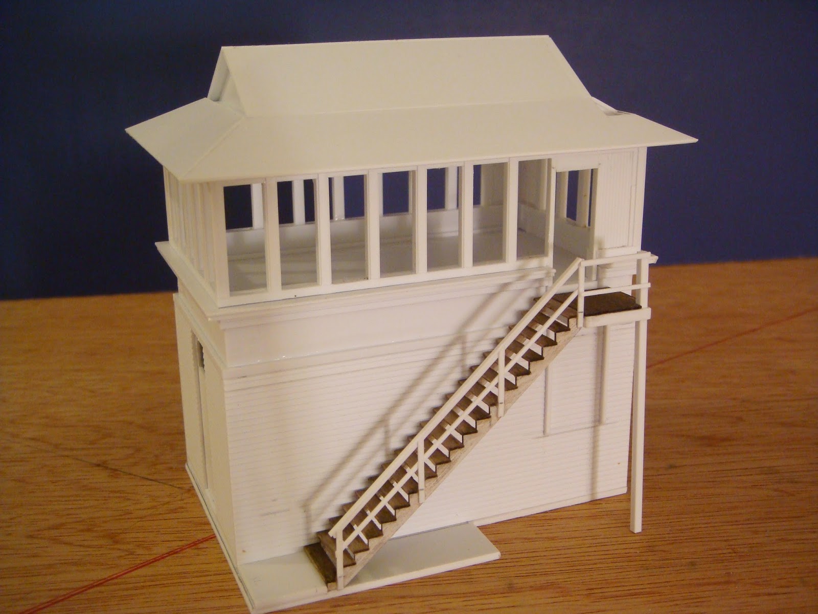
I am in the process of scratch building the tower shown above and below. According to sources from the GTW Historical Society, the tower was closed in late February of 1985 and removed in the late summer of that same year.

 |
| Photo by Charlie Whipp |
 |
| Photo by Charlie Whipp |
 |
| Taken from the steps of the tower. Photo by Charlie Whipp |
 |
| Tappan model board, 1981. Photo by Charlie Whipp |
TAPPAN INTERLOCKING TOWER:
For this build I did not do a cardboard mock up because I already knew the windows would determine the final dimensions of the building. The actual windows are about 20 inches wide, but the closest I could find to this without scratch building was 24 inches wide. The effect this will have is to distort the actual dimensions by about 2 scale feet in both length and width. This minor difference will probably not be noticeable as long as I proportion everything to the larger windows.
The first pic is the start of the two walls that are solid windows. Again these are the two needed sections that will determine the actual footprint of the building.

The next pic shows the other two wall sections. Once the upper observation deck is assembled it will determine the base dimensions.

Here the base has been built so that the upper deck can seat into it. This will allow me to anchor the lower portion to the layout, and still be able to remove the upper portion for detailing the interior once complete. It will also allow me to place any wiring for lighted interior in the base where it will not be visible.

Here the upper deck is seated. There is still much to do on the observation deck. All of the windows will have the mullions removed and painted blue. Interior detail will follow at a later date.

Some additional pictures of progress.


Next the clapboard siding has been installed. I still have not determined what product I will use for the fish scale shingle siding. Next I installed the lower ledge around the base of the upper deck.


I began working on the roof next. Like many railroad towers, Tappan Interlock tower has a Bonnet Roof which is a hip and gable design similar to the Japanese Iramoya style of roof. This complex design took a little bit of planning in order to match the prototype. Rather than trying to cut the compound angles out of a single piece of styrene, I chose to cut two separate pieces to achieve the two different angles. I then glued the two pieces together. These trusses were then glued to the top side of the removable ceiling.


I began working on the stairs by first building a jig to hold the stringers. This makes it a lot easier to glue everything together, and also ensures a uniformed look to the final assembly.


Once the stairs and landing were complete, I then brushed on a coat of Micro-Mark Railroad Tie and Bridge Stain.

Here door and window modifications have been made, the mullions have been removed from all of the windows. Everything is now ready for a primer coat of light gray.

Here the lower roof is beginning to get glued on, and I am test fitting the upper roof sections.

The lower roof is complete. Here the upper roof is fitted but not attached. In the first photo you can see the hole in the roof where the 18 inch square chimney will be mounted prior to the shingles. I have also left enough room at the end of the gables for the fish scale shingles to be mounted. I do not know the thickness of the material that I will use for the shingles, so I left a considerable amount of space (.060 deep) to keep my options open.


Test fitting the stairs to ensure they will line up with the base attached. This will also allow me to determine the height of the main support post.


The handrail has been added to the stairs. For this I used styrene HO scale 2 x 4's for the posts and cap. For the lower rail I used scale 2 x 3's. The stairs are still removable at this point, so I have not connected the handrail to the building. This will happen once the painting process is complete.
The fishscale shingles arrived in the mail. I originally had settled upon the Minuteman Scale Models, N Scale Peel n' Stick shingles. As I was placing the order, on a last minute whim, I also ordered a package of Builders In Scale, N Scale Curved Fish Scale shingles. I am glad I did because the Builders In Scale product is much closer to the dimensions I need for this particular project. The Minuteman shingles will be perfect for the gable ends of houses I plan to scratch build in the future.


I also built the gutters for the roof. The gutters on Tappan tower are much shallower than most gutter / eave troughs I have seen. For these I decided to use .080 Channel with a scale 1 x 4 centered and glued along the bottom to give them depth. These will be painted the same color as the windows and doors.

In interest of saving some time, I recently order some detailing components. For this project I needed a 18"x18"chimney. Normally I hate to order detail components online because you don't necessarily get the best quality component, but rather the first one that the clerk grabs for that item number from the store or warehouse stock. Additionally, and probably the biggest reason for me, is the element of false advertisement. In this case for example I needed an 18" square chimney that would be seen in the interior as well as projecting from the roof. Depots by John had an item that appeared to be more than adequate for this purpose.
The image below is what is advertised on the Depots by John web page.
 |
| 18" Square Chimney with caps HO - 125 2/$3.95 |


For the fishscale shingle siding, I cut a strip of .015 styrene to fit between the clapboard sections. I then used a pencil to draw alignment lines for the Builders in Scale shingles.


After laying the first three rows, I determined that the spacing was a little too far apart and did not match the prototype. The peel and stick backing on these shingles does allow for some movement and I was able to compress the rows without having to waste material. Once I had the shingles in place, I painted them with primer gray to hold them in place and prevent shifting. This was particularly a concern with the top row because after cutting the top edge the individual shingles were no longer kept in alignment by the shingle strip. Here is a look prior to the corner trim being installed.


I next painted the windows and doors. For these I selected Rust-oleum Safety Blue spray paint. This paint has a gloss finish, but repetitive layers of Dull-Cote during the weathering process should tone it down sufficiently.

All glue surfaces have been masked off and primer coat has been applied to all components.

After painting everything white, I installed the windows and doors. Here is a look prior to glass installation and weathering.


Although there is still much to do overall, I am pleased with the way this building is coming along. Once all of the exterior issues are fixed, I can continue with the final weathering. I do not want to install the window glass until the exterior weathering is complete for fear of clouding the glass with sprays of Dull Cote.

Courtesy of Mike Delaney from the Grand Trunk Western Historical Society website, here are some of the original drawings of the Tappan Interlocking tower. I was pleased to find out that my original dimensional guestimates based on old photos of the tower were only 6 inches off in both length and width. Another detail of note is the retrofitted external stairway. The original design featured an interior stairwell. I am not sure what year the interior stairs were abandoned, but the apparent gain was additional floor space for the operator desk on the second level.

I began building the interlocking lever platform and lever locking bed. Tappan used an Improved Saxby and Farmer machine. The S&F design featured levers that extend 4 feet above the floor and are spaced at 5 inch centers. There were 46 lever positions in all at Tappan, but only 44 were in use in the mid 1980's. There is a great deal of detail that I have omitted, but I wanted to at least capture the look of a lever bed and suggest the remaining detail even though the bed in Tappan was generally kept protected under a canvas cover.

The elevated locking bed consists of Longitudinal Locking Bars and Locking Dogs. The bars were connected to the levers and had locking dogs on them. Rather than go into lengthy detail about the inner workings of the locking bed, this interesting site explains everything in detail. It is titled " Principles of Interlocking" http://mysite.du.edu/~etuttle/rail/lock.htm
Here is a look with the final layer of Longitudinal Locking Bars added. I have got the base coat of paint applied followed by some additional weathering powder applications. The actual levers will be added last to avoid the potential of breaking or bending them.

I am still looking for pictures of the actual Track Model Board that would be mounted on the wall above the lever bed. I have heard thru members of the GTW Historical Society that the actual board still exists and is presently located in an office somewhere in Port Huron.
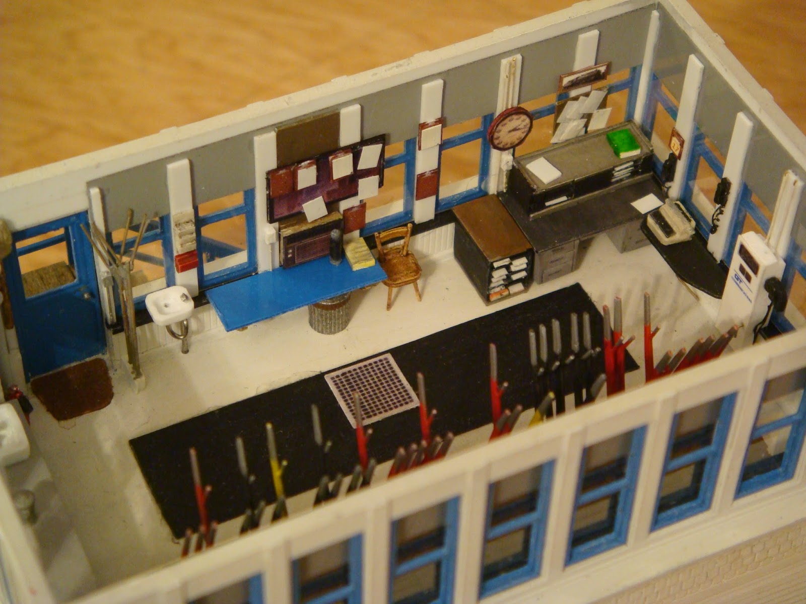
I am beginning to get the interior completed. The first picture of the prototype was taken in 1981 when the interior and exterior trim were painted brown. Later the trim work was painted blue to match other GTW facilities. I will obviously be doing the blue version as can already be seen in the window color.
 |
| June, 1981 |
 |
| 1984 Photo by Charlie Whipp |
 |
| 1984 Photo by Charlie Whipp |
I have installed the wainscot trim work and the lower cabinets along the west wall. In the next few images, the chimney and sink are still not glued in place so I will be able to install the window glazing. The sink still has some touch ups as well which again are not quite as apparent to the naked eye. For the floor mats I will be using photo images glues to the floor. most of the bulletin board data will be photo images as well. I still haven't determined how I will build the levers for the interlocking machine. I am currently experimenting with both brass and styrene versions. Both have advantages and disadvantages. The one with the best overall appearance will win the day.


I finally got back into the groove after the Christmas holidays and fixed the fish scale shingle issue on the tower using a wash of diluted Elmer's glue. Once all of the shingles were secured, I went over the gaps with white paint. I also got the utility shed completed minus chimney and shingles. The shed was located just west of the tower. I am not exactly sure what this shed housed, but it appears to have remained in place all the way until the tower was torn down.

The shingles have been installed on the tower and shed. Next will be the final weathering on both structures before the windows are glued in place.

Gutters and windows have been installed on the tower and final exterior weathering on both structures. Windows still need to be installed on the shed.

The interior of the tower will require time to be able to gather or scratch build details such as type writers, desks, etc...Lighting will also be added. Being able to disassemble the building will help in the process.

The next building to be built is the flat roof structure that sat just to the east of the interlocking tower. According to information derived from members of the GTWHS, this building was actually the communication linesman shop for Tappan. For the time being I will plan on having no interior in this structure. Below is a look at the completed shell. Some of the windows still need the mullions removed, and everything needs to be glued into place. Additional roof venting will be added as well.
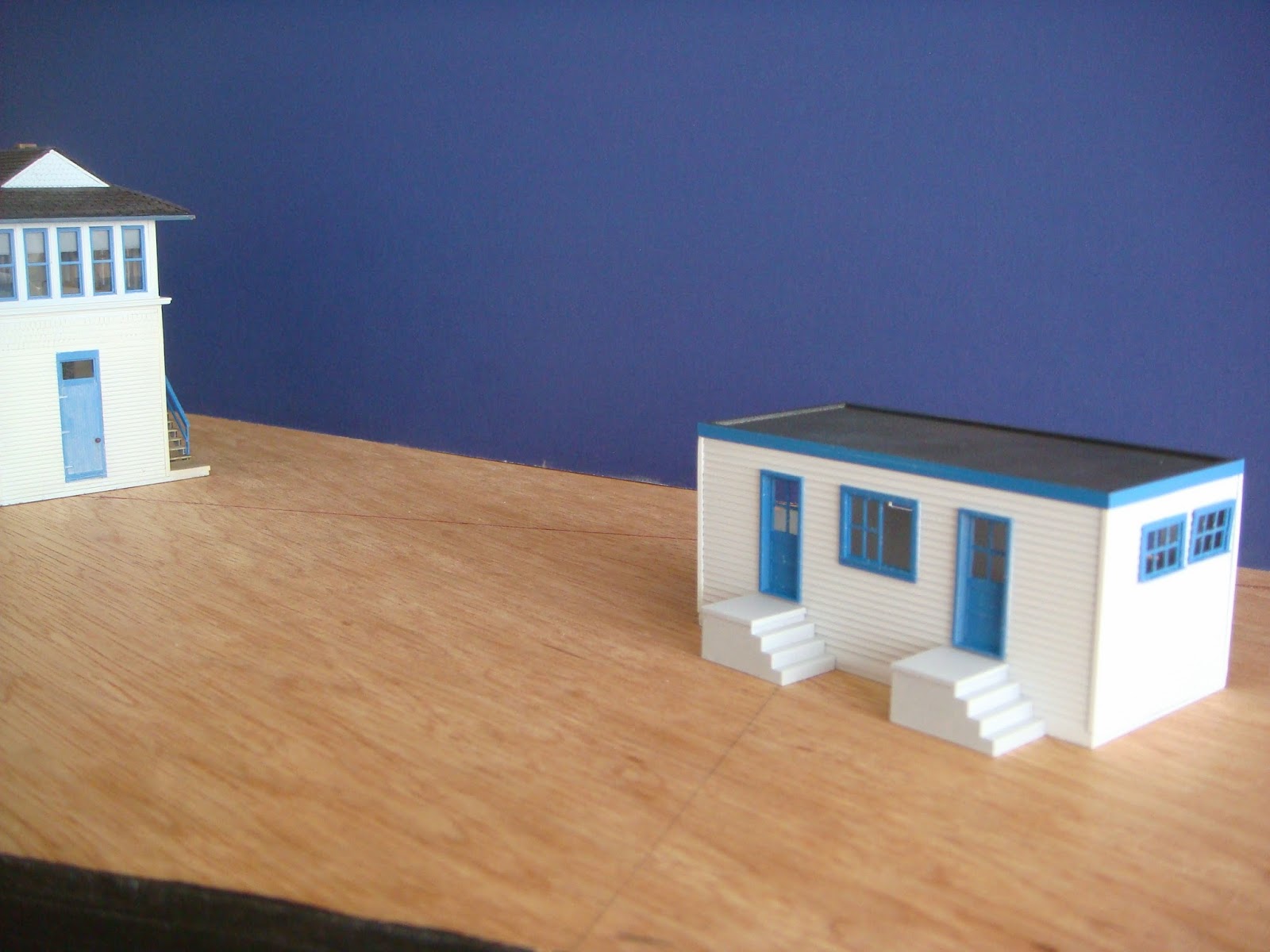

The yard shanty was a quick build. Below is a couple of angles of the completed structure before windows and weathering.


I built the Armstrong levers for the interlocking machine out of brass flat stock and wire. I started by building a jig since I would be doing 46 of these things. I then cut lengths of Detail Associates #2528 Brass Flat Bar .015" x .042". I made these bars slightly longer than necessary so I could cut them to length once complete. I then soldered .016" brass rod to one side with a angled section on the top to represent the locking mechanism, and an extended length out the bottom for mounting into the machine. I then filed a beveled edge on the top to simulate the narrowed handle portion of the lever.

Here are the Armstrong levers installed into the locking bed prior to final weathering. They do not have the exact look I was hoping for, particularly in the handles, but this is only noticeable under macro zoom.


The next two images show the assembled lever and locking bed placed in the tower to get an idea of what it will look like once it is installed. There is still much to do prior to final installation.


The forms shelf to the left of the desk is scratch built from styrene in a similar fashion to the desk unit described above. The train order sticks next to the door were made from brass wire.

More details. I used photo art created on my computer for several of the details including the window AC unit, clock, clipboards, steam engine photo, floor register vent, and the GT communications box. I used .005 styrene thinned even further with a file for the paper forms. In front of the AC unit I added a thermos which was in the prototype pictures. The thermos belongs to Charlie Whipp of the GTWHS. If it were not for Charlie's photograghs, it would have been nearly impossible to get the amount of detail I have captured thus far.
Here is a closer look at the GT communications box.


Although progress has been slow in the summer months, I was able to get the cross bracing added to the exterior stairs. I also added an additional layer of foundation to keep the support posts stable while moving the model.


PORT HURON YARD THROAT:
The yard throat will be visible just before passing into the east staging area. I am still not sure how this will be laid out yet and will not be able to until I am able to build a full size mock up. Most likely this will be one of the last things built so that I can tailor it to my staging design.
 |
| 1983, LOOKING EAST AT PORT HURON YARD. Photo by Charlie Whipp |
 |
| Tappan Interlocking Plant diagram provided by Mike Delaney of the GTWHS |
The Interstate 94 overpass is located just west of Tappan Interlocking. At this point, the Chessie System trackage turns and crosses the GTW as it heads northwest toward Saginaw, MI. The I-94 overpass is a similar design as that of I-496 at East Lansing.
 |
| Chessie diamond, 1984 just west of the I-94 overpass. Photo by Charlie Whipp |
 |
| Track diagram provided by Mike Delaney of the GTWHS |
I finally had time to get the three tables built which will hold the Tappan scene. There is obviously some linear selective compression, but I feel I will be able to get all the essential elements in.

The only modelers license element that I am incorporating will be where the PM
/ C&O crosses the GTW double track. I will be adding a couple
switches here to allow the C&O line to be accessed on the tables.
This will also allow for more flexibility when running with the Sipping & Switching crew.

The sub-roadbed and road bed are in the process of being glued down. I am taking the opportunity to use up a good deal of my scrap luan from previous projects here so it looks a little patchy.

Screws are placed under the rails at the frontiers to prevent de-lamination issues in the future. This is only one of several methods of approaching this issue. Many from the S&SS use brass screws directly under the rails, adjusting to the appropriate height to meet the template. The rails are then soldered directly to the screws.

A technique that I have been using for aesthetics is to epoxy three PC Board ties over the screws.

Next I started laying track in all of the areas that would not have custom track work.

The diamonds started by first determining where the two track would cross. I then measured the angle at 22.5 degrees. This matches the prototype as close as possible. I created a hand drawn template to help with tie placement. Once the template was positioned correctly, I went over it with Double-Sided Scotch Tape.
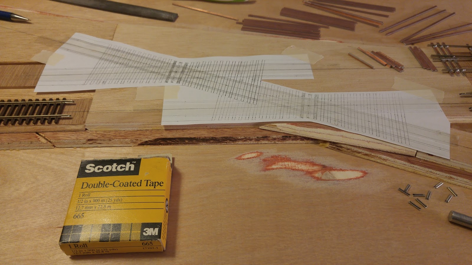
The tape helps to hold the ties in place during the soldering process.

The primary tracks are the first to be soldered in place. The second rail can then be gauged off the first.


More progress on the diamonds with the fictitious connecting track. Both switches are #10, so this should be a very streamlined transition to the C&O trackage.

The yard throat has been started. There is a considerable amount of linear compression here. The first track to the left of the mains paralleled for nearly a quarter of a mile before splitting off to the Dunn paper/Edison Depot Lead on the far left corner.

I was able to get both sections outside to see how the scene is developing. The third section will consist primarily of the lead tracks into Port Huron Yard, and the Mount Clemens Subdivision diamond.


Being that this is an interlocking plant, the normal head blocks are not needed. Instead for these switches I have made the tie between the Head Rod and the Back Rod part of the throw bar mechanism. This I hope will provide some additional rigidity without being too noticeable.

I do not have any photographs of the interlocking hardware of Tappan, but the following pictures taken from Hancock Interlocking Tower, Maryland found online show the detail of this component. I am still unsure of the original photographer and will credit the photos once I do.
 |
| Facing Point Lock details. Photographer Unknown |
 |
| The GRS Unit will be omittted for Tappan. |


Recessed switch throws are finally complete. After testing several sized holes on a piece of scrap, I went with a 2 1/2 inch hole for these. The knobs which I purchases from a vendor online, are 1/2 inch wide and 3/4 inch deep. This leaves sufficient space for sausage fingers to be able to operate the throws.


Located about 2 miles west of Tappan Interlocking is North Wadhams Road, also known as West Tappan (Kimball Township). This is the point that the mainline narrows to one track and remains single track all the way to East Flint. This module, and the other modules between Tappan and Emmett will be as shallow as possible to save space. I intend for them to be no more than 18 inches deep which will be sufficient to capture the open country feel between towns.
 |
| Photographer Unknown |
"Well ya know, building raised roadbed is a complete waste of time because you can't see it anyway."
ReplyDeleteOr at least that was what I was told by someone who shall remain nameless. Many years ago I had a guy ask me what shade of green I though UPS trucks were painted. It was then that I realized that this person was colorblind. You can't model what you can't see.
Mark