


 |
| Lansing River crossing and 496 Overpass |
I started designing this module back in late 2011. I knew what I wanted in my home layout, but wanted to also make it compatible with the S&SS group. The one area that I was not willing to compromise was in altering the prototypical track arrangement. By doing so though, my modules become a planning consideration when plugging into the S&SS network. Some of the biggest benefits to my overall approach to constructing my home layout modular are that...
1. It can go wherever I go and I can continue building toward my ultimate end state.
2. I don’t have to feel overwhelmed at any point during construction because I can work on as big or as small of a section as I desire.
3. I can test each section as I complete them...by running 100 plus car trains across them.
I identified the key points of visual interest that I wanted to capture and then began the process of selective compression until I was happy with the overall scene. This allowed me to determine placement of the Z frame which is needed for the Lansing River crossing and raised fill.
The old GTW coal tower was the first structure I built. Going through the GTW Historical Society, I was able to get elevation blueprints for the tower.

At this point it is still in the styrene core assembly.
As many may have noticed, I have many structures that are in varying stages of
completion. This has been a conscious decision in order to GET TRAINS RUNNING.
Structures take the most time to complete in a scene. It doesn’t matter if they
are scratch built or kits. Once the scene is complete, I will be able to go
back whenever I am in the mood to work on or complete each structure to my
liking.
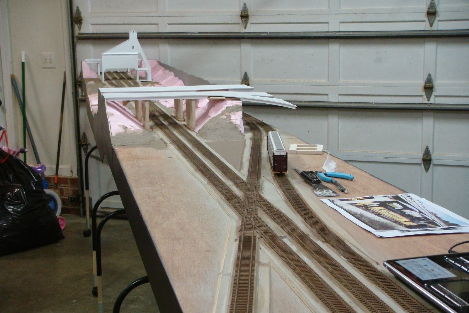
Once I had determined
the final layout of the module, I put some test track down and began tinkering
with some rolling stock (pushing it around and basically conducting a sanity
check of my final plan).In this photo, I have placed my highway pier castings. This is where Interstate 496 crosses and the off ramp to Trowbridge Rd starts. This needed to be compressed slightly but I wanted the visual impact of the off ramp.

I used some modeler's license here in the routing of the C&O trackage. On the prototype, the C&O continues straight NE from the diamonds, with the interchange track ending prior to passing under 496. I opted to slightly curve the track as it passes behind the backdrop in order to extend the interchange track. The track runs to the end of the module which also allows for future expansion into staging,, etc...

I hand layed the diamonds next.

My hand layed track is getting better the more I do. I
have always told anyone who says they "can't" do something in this
hobby that the only way you will be able to...or get better, is TO DO IT! I was
very proud of my first hand layed track, but when I look back at it now I
cringe. But...when I compare them to my work now it is obvious how far I have
come along...and still learning always.
Here the backdrop is
being tested. It will hide the interchange track.


I have elected #10 switches to be the minimum standard for my main lines. On the Grand Trunk, over 50% of the traffic is auto related which equates to long pieces of rolling stock. Although a #10 is still not long enough to be prototypical for mainline cross overs, it is enough to handle the longer equipment reliably. I am currently using a Fast Tracks template for my #10's. I felt the purchase was justifyable since I will be needing a bunch of turnouts.

I had to make sure to allow adequate space for the Blue Point switch machines to be installed. These will be operable from both sides of the module so there is no need to duck under or...more importantly, no need to reach over to throw a switch.

In planning the Interstate 496 overpass, I had to make
the decision to compress the back side where it crosses the C&O. This is a
sloped embankment on the prototype, but I opted for a straight wall abutment.
This will also help in hiding the entrance to the staging track.

Once all the track was in place, I dug out some long
pieces of rolling stock...and a few others because I couldn't resist...to start
testing the trackwork. The idea is that if transition ramps into sidings or
along any elevation change can handle long cars such as autoracks, autoboxes,
passenger, etc... without uncoupling, they can handle anything reliably.

Once satisfied, I dug out some power and tested the electrical.

Since inclimate weather would not allow me to get the track painted yet, I pushed forward with structures. Test fitting and adjusting final height.
Aurelius Road crosses just west of the coaling tower. I scratchbuilt my bridges in order to give the scenes a more prototypical feel. Although there are many good bridge models on the market, I wanted to capture a look that is common place along the GTW ROW. One of the biggest visual details is the concrete guard rail design. This bridge guard rail is the Michigan Open Parapet design. I made a simple jig to allow me to mass produce the design. I have not yet added the top steel rail because I have yet to "crack the code" on the curved short stanchions used on many of these bridges.

These are the stanchions I will be attempting to mass produce. Building one is easy enough, but I will need about a Bazillion (a lot) because nearly every bridge up there has them. In the two pictures below are additional views of the Michigan Open Parapet style guard rail. The concrete barrier is topped with a 4 inch aluminum safety rail supported by CA1-2 aluminum posts.


The Lansing coal tower.


I use rattle can spray paints for the base coat. I used up what I had left of Testors Flat Light Aircraft Gray. Lately, I have been using Valspar Hunter's White for my base coats. The Valspar is a satin finish, but I was not concerned with this as there will be so many subsequent layers of washes and dullcote that it will not matter.


I then began getting my final contour for the terrain.


Here the foam is shaved back from the seam.


Next I began covering the terrain with Ground Goop. ( See MISC page - Ground Goop)


The base color near the track was painted black to represent cinder sub road bed. Most of this will eventually be covered, but there always seems to be that one spot that doesn't cover well.


Here, the Lansing River bottom was contoured. I plan on using the Magic Water for the river. On the right you can see where the Lansing River walking trail passes under the GTW ROW.

For Aurelius Road, I needed to set the abutments in place to accept the bridge. I began by placing all of the components on the slope and then adjusting them to fit the bridge. Once I had the final location I marked everything in pencil and shaved the foam slope to the proper angle.


Once I determine the track configuration, I determine the track height. For the mainlines on Trowbridge, I use beveled luan for the sub-roadbed cut to the appropriate width to raise both tracks. Another layer of beveled luan is used for the roadbed, cut for each individual track. You can see a good cross section of this above where the module is in my driveway prior to painting. The interchange track drops down one level of luan at the east end (side with the buildings) and continues to drop down an additional level all the way to the deck just prior to passing under the highway. The C&O mainline is also dropping elevation at this point as it continues behind the backdrop.
For raised fills, such as the river basin, it is better to just drop the entire base which is what I have done with the "Z" frame sections of the module.
Next on the agenda was to get the view block painted. I started with an old can of light olive green over the primer coat.


Next I painted the basic forest canopy over the base.


Aurelius Rd Bridge received a primer coat in the middle of ballasting. To the left in the photos, you can see where the hidden track runs to the end of the module under Aurelius Rd. This will allow for possible future expansion, as well as connection to staging on my home layout.


For the bridge piers (bents), I scratchbuilt a master and created a mold. I then cast the piers out of Alumalite Liquid Casting Plastic. This will allow me to cast piers for future bridges as well. Superelevation Pedestals have not been added to the piers yet. I will be doing this with styrene layers to match the abutments.


Ballast always seems to be a big topic of discussion in terms of techniques for laying it down, composition, size, color etc... I will go over how I chose to tackle it here, but I am not suggesting my way is the way it is done.
I approach ballast the same way I do any other scenery layer. It is my opinion that one of the keys to successfully capturing a realistic looking scene is variation in size, color, etc...When painting concrete, there is no ONE color, but a collage of colors that blend and present themselves to our eyes in a way that we interpret as a solid color. In actuality, our eyes are picking out the dominant colors. I think ballast and ground cover are the same.
People always ask what size is appropriate for HO scale? Medium or Fine? Personally, I think BOTH fit the scale, and I have seen numerous examples to support both sizes along the GTW ROW.
That said...
To get the ballast colors, I studied a number of photos of the area and broke down what I determined to be different zones of color patterns. Mainlines vs. sidings, different ownership of trackage (GTW, C&O, etc). I took one zone at a time. I then picked what I believed to be the dominant colors in the zone. From there, I started mixing my colors.
For Trowbridge, I used almost predominantly Woodland Scenics ballast. I mix my ballast in clear plastic peanut butter jars...minus the peanut butter. I use an old powdered drink scoop, but anything will work. Starting with the medium ballast, the dominant colors get 2 or 3 units of measurement each. Any other colors get 1 scoop each. I then seal and shake. Once I have a uniform blend, I compare it to photos and adjust as necessary keeping good notes of my mix. Once I am satisfied, I mix an identical batch of fine ballast. I number the top of the jars and keep a log of the formulas in each. I will do this with each zone.
For application, I believe the key is in thin layers. Rather than try to cover everything in one pass, I apply two shallow layers no more than a few stones deep. Starting with the medium ballast, I lay the first layer over the cinder roadbed. Without gluing the first layer, I go back over with a shallow layer of matching fine ballast. Then I glue both layers at the same time.
Woodland Scenics ballast as most are aware in actually ground walnut shell. When glueing it down, many have problems with the ballast floating. The trick is a good wetting agent prior to the glue, and lots of it. Find a spray bottle that puts out a fine mist. I use an old hairspray bottle that creates a very fine mist. My mix is about 30% Windex, 30% isopropyl alcohol, and 40% water. Starting about 3 feet above the track, I will start spraying the mist horizontally along the track instead of straight down. Keep pumping, and gradually lower the mister closer to the track. Once I can see that everything is saturated, I know I am ready for glue. USE whatever glue mix you are comfortable with. If the glue doesn’t penetrate the ballast, then it is not wet enough. Reapply mist and try again. I didn’t get progress pics of these techniques, but here are some pics of the results.


Again, there was a lot of selective compression here, but I tried to capture some of the signature structures of the area. An example of selective compression is the two office buildings on the left. On the prototype, there are four of these buildings in a row. When you stand at the diamonds, you can only see two. Likewise, when you stand on the Amtrak platform further east, only two are visible. I simply omitted two of the buildings to gain real estate.


The next structure to the right of the office buildings is the two story Michigan Department of Transportation building. The name is on the street side and the perspective on the model is from the back side so the name is unimportant. This is a prominent building in the area that can be seen from a distance. I had omitted two additional buildings that were located between the MDOT offices and the two smaller office buildings. One was an insurance company, and the other a Taco Bell that did not exist in the 80's.


Using the parking lot of the Korean Market as an example:
First I cut a piece of .060 sheet to the rough dimensions of the parking lot. In this pic, I have also layed out the southbound lanes for S. Harrison Rd. I then draw onto the sheet the locations of the parking lot, sidewalks, etc...


On the topic of roads, it is my opinion that one of the biggest killers of model railroad scenes is unrealistic roads, parking lots, loading areas, etc...The problem is...or seems to be this. The modeler gets an idea of a roadway scene in mind, and feels it must be modeled in its entirety on the layout. Roads modeled to scale take up a great deal more real estate than one would think. To get a good idea, go to a DOT website and look at the standards for whatever it is you are trying to model. Don't just look at lane width, look at minimum shoulder width, curb sizes, etc...We spend so much time making our R.R. ROW's look believable but don't do them justice by putting a substandard roadway next to them. I always go by the idea that if it doesn't completely fit on the module, who cares? Run it off the edge of the module. As long as it is modeled realistically, the mind assumes the rest.
Parking lots and loading areas are the same. If there is a loading dock that is used for loading goods into semi trailers, but no way that a semi trailer can possibly get to it, then it looks screwy even if it is not completely obvious what the problem is. The eyes pick out that something is out of whack.
The way I go about planning is to first determine the desired scene. Then I consult the Michigan DOT and see what is required in terms of space. I then adjust my plan to conform to the actual layout space. Often this means omitting things, but the results of a compressed scene should not sacrifice realism. Once I have my plan drawn, I spend some time "playing" with model cars and trucks to see if they could actually negotiate the travel ways.
This pic shows the parking lot / street side of the Korean Market.


Another look at the front side of the Amtrak station. The styrene sheet to the right will be the front parking lot.It is difficult to tell in this pic, but I have drawn the locations of the curb and raised planter bed.

In this photo, the curbs and sidewalks have been sprayed their base color. I used the Walthers rubber grade crossings here. I have no idea why Walthers did not cast these things in BLACK plastic. When installing them, allow as much clearance as possible on the rails. I have mine lowered significantly and still have issues with the gray plastic showing through after running a Bright Boy over the rails.

For overall scene composition, I look at images of the area I am modeling and determine “what are the key visual components to the scene that set it in time and place”? This helps me in deciding which structures will need to be built. I then determine if there are any existing kits of components that will speed up the process…only have 100 years to live…
When beginning any new structure, I start by gathering as much known data as possible about it. This may come in the form of elevation blueprints, photos from online sources, personal photos and measurements, etc…In recent years; I have used Google Earth and Bing Maps extensively as well, particularly when trying to see what is on the roof of a structure.
If actual measurements are not available, I will try to find photos from all four sides and print them out. I then pick something with a known dimension and start writing dimensions onto the photo. Doors are often the best bet since they are generally around 80-82 inches tall. Measured to the top of the trim and they are usually right at 7 feet. Using an index card, I will then make a scale rule for that photo. It is easy to then determine the remaining measurements. I continue doing this with all remaining photos and keep the scale rule labeled for each particular photo.
At this point, I will draw the building to scale on a piece of cereal box card board and make a mock-up. Once the mock-up is on the layout, it is easy to determine whether or not it will need to be compressed. Again I am looking at it from a scene composition stand point here. I don’t want any one element to overpower the scene. I want it to blend into the overall setting.
For Trowbridge, most of the buildings are in the background and will not have a detailed interior. In this case, I can get the basic box structure built rather quickly. For this I use .060 styrene that I purchase in 4x8 ft sheets from Piedmont Plastics. Remember when building the box to compensate for the thickness of whatever you are going to veneer as the final fascia (brick, cement block, etc…) multiply whatever that thickness is by 2 and subtract that from the dimension. If a window or door is to be facing the viewer, I generally cut it out and create a shadow box behind it to give it depth. You just have to suggest that the interior details are there. Buildings with full interiors are roughed in the same way, but more planning goes into the interior layout obviously. In most cases, the biggest slow down for me in planning interiors is the lighting/electrical. It is not a matter of how will I build it, but rather HOW WILL I MAINTAIN IT? When a light bulb or LED burns out, there needs to be a simple solution for replacing it…otherwise it probably won’t get done.
I like to put my structures on a .060 foundation if possible. Once I determine the final location of the building on the module/layout, I use strips of .060 styrene to build a pocket that the foundation will seat into. This does two things. First, it makes it easier to mount the building and get it in the exact same place any time you remove it. Second, the scenery base comes to the top of the .060 strips and covers them up. The building then plugs into the scenery so there is no chance it may look like it is sitting on top. This is also helpful for lighted interiors as the light can’t escape under the walls. An example of this technique can be seen with the Korean Market building. The sidewalks around the building form the pocket that the structure seats into.
My goal is that anyone who has been to the area I am modeling will instantly recognize the location without even looking at signs or labels. I was very happy with Trowbridge when a gentleman came up to us at a train show in Raleigh, North Carolina and asked “Who here is from Michigan? Who did Trowbridge over there?” At the time, all the buildings were plain white styrene and there were no signs anywhere. MISSION SUCCESS!!!
More work on the two story Michigan Department of Transportation (MDOT) building.
I painted the whole building with the base mortar color and then colored the brick using colored pencils. The windows will be painted black before applying the glazing. All of the lighting will be exterior security lights when complete.


These photos show the building in it's completed state with only minor weathering and exterior security lights left to be added.


The actual building

Progress on the Asian Market. The roof is removable.


The windows have been cut out of the store front. This should have been completed prior to assembly, but originally I was going to have reflective windows to hide the fact there was no interior. After further consideration I have decided that since the building will be at the end of the module where it may be viewed at some point from various angles other than what is intended on the home layout, I will include a shallow interior.
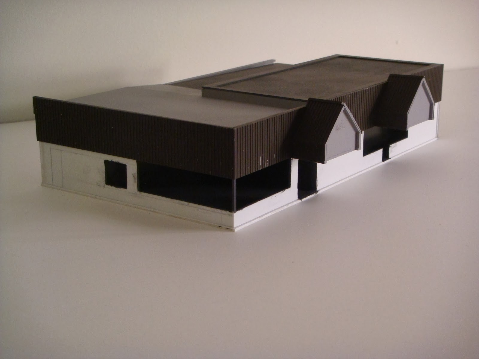


The roof is complete for the warehouse, but will need to be faded and weathered along with the rest of the building.


Beginning work on the GTW Coal Tower. The first three pics show the unpainted styrene model.


The next two pics show the base color applied. I then use a pencil to shade the areas which will require spalling.


Here the initial spalling has been applied with a Dremel tool based on various pictures of the prototype. These will continue to be refined and improved upon as the work progresses.


I came across your blog for the first time this week and just about fell out of my chair! The accuracy and attention to detail in your modeling is absolutely superb. You have recreated Trowbridge with incredible precision. I plan to model a portion of the GTW Flint Sub someday too, although a smaller portion than you are taking on. As of now I’m planning to include Charlotte, the Lansing Car Assembly area of Lansing, and Trowbridge. The information on your blog is a gold mine for me, so thank you for posting it!
ReplyDeleteAs far as modeling the roadway overpass guard rail stanchions, I’ve thought about using Athearn Blue Box locomotive handrails. If you want a more accurate stand-off you could try bending the handrail post into the triangular shape and filling it with something. I’m not sure how mass-producible that would be, but just a thought.
I look forward to following your progress!
Matt,
ReplyDeleteThanks so much for the comments. It sounds like we will probably be able to share a lot of information when it comes to traffic generation for operation. The sidings at Trowbridge for example were used to store freight cars for the Lansing Assembly plant. Thanks for the idea on the guard rail stanchions. I am still holding out for something that can be mass produced. I will have several more bridges to do and producing each one of these individually will be too time consuming.
I'm working on the other side of this, CSX. I hope to include Trowbridge in my layout. This is fantastic!!
ReplyDeleteJeff, I just found this. Man you are doing a KILLER job on these sets of modules. Just beautiful!!!!!!!
ReplyDeleteThe progress you have made since I last saw it is great!
Thanks Brian. I have been making progress in so many other areas that I haven't had the opportunity to get these set back up to work on. I hope to soon as the fall weather allows me to get outside to work. Now if I could only do diesels as well as you...lol.
DeleteHi fellas,
ReplyDeleteThank you so much for this wonderful article really!
If someone want to read more about that Trowbridge I think this is the right place for you!
Hey Jeff! I know im a little late, but this is great! Super detailed! I love the buildings, especially that warehouse. It just looks so realistic. Well, I doubt you'll see this, but I hope you know you're work is appreciated, even 11 years later!
ReplyDeleteNIROZ I appreciate the complements and yes, I am back up and running on the blog. There was a period of time that I was unactive on this site due to a platform shift by the blogger site. Then when they shifted to Google, I was able to post again. I also have the Facebook page set up now for capturing what is happening with the build. The blog site will be the deeper dive into how it was done.
DeleteGreat! Its cool at you're still active. I'll try to find the Facebook
DeleteNice Blog
ReplyDeleteself balancing wheel weights in Delhi
The discussion serves as a collaborative archive, as commenters filled in gaps regarding specific locomotive types and the precise timing of various track reconfigurations over the decades. It’s clear from the thread that Trowbridge remains a sentimental landmark for the community, representing a golden era of Michigan’s industrial rail heritage. View more details from Concrete Contractor Augusta
ReplyDeleteThe discussion also functions as a digital archive of a bygone era, as commenters swapped stories about the unique "diamond" crossing where the GTW and CSX lines met. It is a classic example of the niche historical blogging community, where the shared passion for locomotive history turns a simple post into a collaborative effort to preserve the industrial heritage of the Flint Subdivision. Find out more about Concrete Patio Port Saint Lucie
ReplyDeleteNice post!
ReplyDeleteConcrete Patio Clearwater
This niche community clearly values the project not just as a hobby, but as a collaborative effort to preserve Michigan's rail history. It provides a fascinating look at how digital platforms can sustain long-term engagement across decades of hobbyist development.
Trowbridge remains a landmark of Michigan's industrial history, acting as a crossroads for both freight and the passengers of the Blue Water Amtrak line. It is a site where the echoes of the old Grand Trunk Western are still very much felt by the local community. See more - Fence Company Augusta GA
ReplyDeleteThe amount of detail and craftsmanship in this layout is outstanding. From hand-laid track to custom bridges, scenery, and structures, every element contributes to a realistic scene. The attention given to concrete textures and infrastructure mirrors the quality seen in Concrete Driveway and Foundation Specialists where accurate details make all the difference.
ReplyDelete