
 |
| FLINT 1983. Photo by Don Ross |
Flint was once the second largest automobile producing city in the nation. Much of the Flint auto industry is served out of Bristol and Torrey yards, as well as the handling of all through freight from Port Huron and Canada. General Motors requires a “just in time” delivery system in order to meet the production demands of the many GM plants serviced by the GTW. All together, these plants generate an enormous amount of traffic for the Grand Trunk.
GTW’s old mainline through Flint is severed, but still serves several large plants. Switch jobs out of Bristol Yard facilitate the movement of products and material between the plants and the yard.
Ronald Jackson a member of the GTW Historical Society had posted several of the old car control zoning charts of the Flint area. These have been very helpful to me and utilized in conjunction with the GTW track chart (also available from the GTWHS) has made it much easier to piece together operations in and around Flint.
 |
| FLINT TERMINAL MAP. From 1973 GTW Car Control Manual. Provided by Ron Jackson of the GTWHS |
General Motors Truck and Bus Assembly Plant:

Torrey Yard:
Torrey Yard is located along the south side of Interstate 69 on the east side of Interstate 75. This yard is used for marshaling traffic to keep up with the demands of the GM assembly plant. The main body has 9 tracks which are primarily used for holding frame loads, stamped panel loads (86ft Boxcars), and empty autoracks. The yard office was located on the north side of the mainline at the bend in West 12th Street / South Ballenger Highway. The vehicular entrance is still there however the yard office has been removed. In its place is a cellular tower. After the Torrey Yard office was removed, it was replaced by David Rd Tower which was located on the south side of the yard further in toward the plant.
On the west end of the yard, is a 6-track auto loading facility that holds up to 30 autoracks.
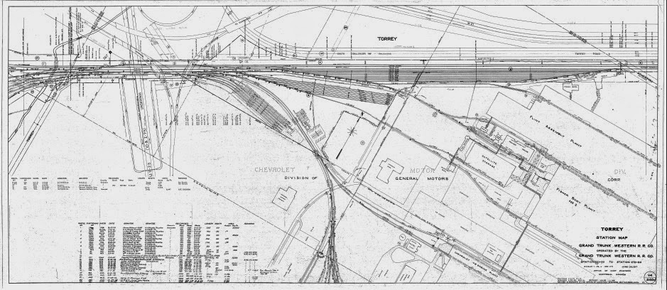


The photo below shows most of Torrey Yard. Fisher Yard is where the string of boxcars are spotted. The location of the old Torrey Yard office was in the foreground where the vehicle turn around can be seen at the base of the cell tower. The new David Rd Tower was built further into the plant complex and can be seen just to the right of the telephone pole in front of the autorack loading facility.
 |
| TORREY YARD |
 |
| TORREY YARD viewed from Ballenger Highway |
 |
| GM Truck and Bus autorack loading facility |
Fisher Yard as it was called by rail hands is a smaller 7 track storage yard that runs along the southwest end of the main body that is used for storing loaded 60ft Boxcars with parts to feed the Fisher Body Plant #2.
 |
| FISHER YARD in the center of photo. Photographer Unknown |
ZONE T:
The bulk of the switching for the GM plant occurred in Zone T.


ZONES N & S:
Bristol Yard:
Bristol Yard is located on the west side of Interstate 75. Bristol is comprised of two large classification areas designated as north and south yards.
North Yard is adjacent to the mainline which is double track with two additional arrival and departure tracks. North Yard itself has a 17-track classification area.
South Yard consisted of a larger 28 track classification area. Running down the center of the two was a single track appropriately named Center Track. This track was considered part of the north yard because it stemmed from the north yard throat. It is actually a remnant of the original mainline.
Along the southeast corner of the yard were the car repair shops and engine service facilities.

Bristol North Yard (ZONE N):
North Yard handled all outbound traffic as it was pulled from the automotive plants. Center Track was often utilized to build outbound trains before they were dropped on the setout tracks (N21 &N22 in the diagram below).


Bristol South Yard (ZONE S):
South Yard handled all inbound traffic...


The picture below is a view from Bristol Tower of South Yard looking east. Note the rerouted Bristol Road being worked on at the far right. This picture was probably taken in the mid to late 90's.
 |
| BRISTOL YARD looking east from the yard tower. Photographer unknown. |
 |
| Bristol South Yard in 1983. Photo by Jack Smith |
 |
| BRISTOL YARD TOWER 1984. Photographer Unknown |
 |
| BRISTOL YARD TOWER. Photo by Dennis Clark |
Car Shops and Engine Service Facility:
Located at the east end of Bristol South Yard is the service facility that handles both locomotives and rail cars.


ZONE O:
GM Service and Parts Plant:
This plant was serviced by the GTW along the old mainline enroute to Chevy in the hole. Otterburn Yard, which was an 8 track storage yard, ran along the back / north side of the plant and was used to spot auto parts boxcars to keep up with the demand of the plant.


 |
| GM Service and Parts Plant |
 |
| OTTERBURN YARD with GM Service and Parts Plant in the background. |
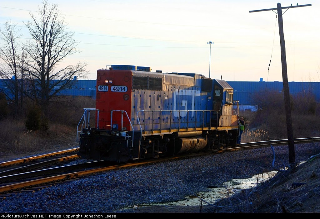 |
| Working the GM Parts Plant. Photo by Jonathon Leese |
ZONE R:
Corunna Road Yard:
Chevy in the hole demanded a great number of auto parts boxcars but was never intended to see 86ft Hi-cubes. Stephenson Road Yard, which was located along the southeast corner of the plant was used to stage inbound and outbound traffic. This yard was too small for the massive Hi-cubes however, so these were stored a few miles west upgrade at Corunna Road Yard. They were brought down to the plant as needed, and as soon as they were pulled from the plant, they were quickly pushed back up the hill to the Corunna Rd Yard. Corunna Rd Yard consisted of 10 body tracks and a team track. It was also co-located with the Central Grocery distribution terminal which was serviced by the GTW.


 |
| Photo downloaded from RR Picture Archives, Photographer Unknown |
 |
| Photo downloaded from RR Picture Archives, Photographer Unknown |
ZONE M:
Chevrolet Manufacturing Division, Flint – “Chevy in the hole”:
Selectively compressing this plant will be a challenge. Modeling the complex at 75 percent size will equate to a 40-foot-long peninsula. Although this is indeed large, I feel it will be sufficient to model a good portion of automobile traffic indicative of the GTW. The research with this particular project has been enjoyable. There is an incredible amount of history in this complex. I intend to represent traffic volume as it was in the 1970's.


ZONE E:


James Lumber Company, as seen from overhead imagery still shows a shadow of the spur track. This business is located on Fenton Rd just west of GM Truck and Bus.

Fenton Road:
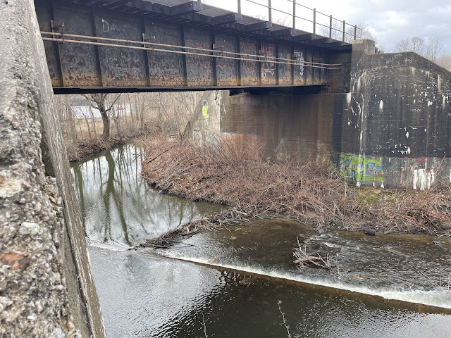
The very noteworthy "Grand Funk" bridge over Fenton Road, made famous by the namesake 70's rock band from Flint, MI. At some point in the early 80's the Grand Trunk bridge was vandalized to show the name of the band. Mark Farner and Don Brewer were two of the founding members, however Dennis Bellinger did not join the band until 1981 replacing Mel Schacher on bass.

When I was happy with the degree of deterioration, I sanded the entire surface using a circular motion in order to avoid lines.

Once the stanchions were all drilled, I began glueing them in place. I used a straight edge to ensure alignment. It was then test fitted into the abutments.


With the handrails in place, I did a final test fit and then cut the extended ties for all four approaches. In the photos I could see that the last 4 crossties on each approach got progressively wider with the last one being full width of the bridge. In addition, there is a full width tie that sits on the top of the concrete abutment. Once these were cut, I finished painting the track.

Sifted black soil was added onto the fill to represent the cinder sub-roadbed. This also helps to give some tooth to the slope to allow the following layer of sub-roadbed ballast to cling to the fill while being glued.


Once my cinder base had dried, I began applying the ballast layers using my custom mixes for the GTW Mainline. The sub-roadbed layer depicts older ballast which is darker in appearance as can be seen here in the image below. The top layer being the newest is also the lightest in color.


Moving my attention back to Thread Creek, I then glued the dam in place using a board and weights to make sure that everything stayed straight and flat. This is a new technique I am experimenting with for the creek bed. The entire thing is removeable so I can work on the details away from the module. Once done I will set it in place and profile the fascia edges to match the creek. After all the cutting is done I will glue it in place and doctor up the transition. I still need to create a test pour mockup as I did with the Shiawassee River pour to look at color selections and more importantly, multi-height pours. This scene will feature four different water heights. The beaver dam backs up the creek causing it to flow over the dam. From behind the dam the water drops again to the area below the beaver dam. It then drops slightly a third time over a small secondary debris dam downstream from the beaver dam. This should be a fun project.

Next up I masked off the stanchions and handrails for the bridge and painted them the same Aluminum color as the bridge girders.

I had originally left room for the control point signals when I spaced everything out, but I had forgot to put the mounting pads in when I did the initial roadbed. I went back and glued these in place. These areas are supported on the side of the fill with steel piling retaining walls which I have designed for 3D printing.
Base colors were also applied to the Thread Creek bridge. I used Tamiya XF-1 Flat Black for the bridge girders. For the abutments I once again started with Valspar Hunters White the same as I had used with the Shiawassee River bridge in Bancroft.
With the base colors applied, it was now time to move to the abutment weathering. For this I use a multi-layering process which is time consuming, but the end result makes it well worth the time and effort. As I list the steps below, note that each layer is sealed with Dull Cote or equivalent.
Now that the powders have all been sealed in place, I turn to acrylic layering of the wing walls which show a significant amount of spalling and deterioration due to time and water damage. I use the same acrylic colors as the washes above; however, these are applied using a smaller brush and are painted on heavier to depict desired placement according to the prototype photos. Once again, acrylic craft paint colors used are White, Sand, and Quaker Gray.
Once the acrylic layers were in place, I sealed everything in preparation for the dark wash layer which highlights and enhances the surface detail.
After the dark wash layer, I turned to colored pencils to depict some of the finer details.


Dort Highway:
The Dort Highway bridge has an interesting art deco design...


Flint Mass Transportation Authority (MTA):
C&O Crossing:
Just east of Flint Amtrak, the GTW crosses the Chessie (now CSX) double track main.

ZONE V:
Belsay Yard:
This was one of the original yards in Flint which served the automotive industry.


041303%5BDaleBerry%5D.jpg)
ZONE C:
AC Spark Plug:


ZONE D:


James Lumber:
Just to the west of AC Spark Plug, immediately after the crossing of the double track C&O is James Lumber. This is a simple industry that consists of a single spur track for the spotting of forest products cars near the storage facility.
MODELING FLINT:
I was able to get a copy of the elevation blueprints from the GTW Historical Society for the Bristol Yard Tower. Since I knew I would be building this structure full scale, I bypassed the cardboard mockup and moved ahead with the styrene core of the building.
BRISTOL CAR REPAIR SHOP:
The Car Repair Shop, located in the service facility area at the east end of Bristol Yard is a sizable structure. The main building, which was added in the early 1970's, is 70 feet wide and 220 feet long. The inner work area consists of two tracks each with 11 different 20-foot work bays (total of 22 work bays). This large steel structure is attached to the side of the old pre-existing repair shop building that is located along the south side.
The very noteworthy "Grand Funk" bridge over Fenton Road, made famous by the namesake 70's rock band from Flint, MI. At some point in the early 80's the Grand Trunk bridge was vandalized to show the name of the band. Mark Farner and Don Brewer were two of the founding members, however Dennis Bellinger did not join the band until 1981 replacing Mel Schacher on bass.
C&O Railroad Crossing
S. Grand Traverse St and Thread Creek


By increasing the gauge of piano wire to .054, I was able to drop the Blue Point down using a 2-inch standoff mount. This allows the mechanism linkage to be engaged much easier from below the deck.

For this project I will be creating my own bridges over Thread Creek and S. Grand Traverse St. using components from two Walthers 70ft single track deck girder bridge kits, both PC board and wooden ties, and scratchbuilt abutments.

 Here I'd added .250 x .250 styrene for the upright columns, the bridge seat, and the remainder of the abutment body. The evenly measured increments between each piece gave me a base to start building up the 1-12 batter.
 I continued to add more styrene and the incremental stair-steps for the batter.
 The final doubled up layer of .060 styrene brought the abutment to its final form. This .120 thick final layer will allow for strength as well as depth for spalling and detail work. I added additional stair-stepped styrene to the upright columns as well.
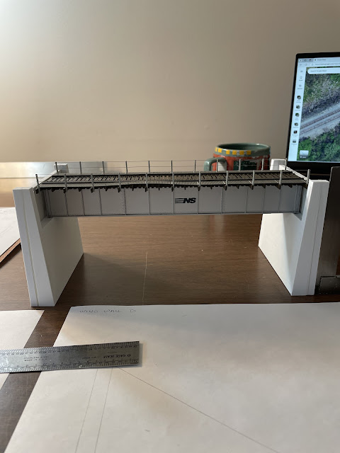
After adding more column depth to the backside, I then sanded the front and sides smooth. After I had repeated the process for the second abutment, I did a small mockup using an Exact Rail girder bridge as a stand-in.

I then build the wing walls using the same process of stacking. The wing walls can be built flat and do not require built-in batter. They will be angled, offset, tilted and glued in place to match up with the batter of the abutments.


The southern wing walls have been resurfaced at some point, perhaps more than once. The resurface material has cracked along most of the original underlying concrete. For these cracks, I first drew straight lines with a pencil and ruler, and then hand traced the path with my Exacto knife. I also outlined the areas that would be spalled using the Dremel tool.
 Once the pitting and spalling were complete, I sanded the surface again. The grooved styrene is still present at this point, but the prominent edges formed by the cutting are eliminated. They will show later when washes are applied over the area. I then test fitted the wing wall against the abutment and marked the areas where the spalling runs over onto the abutment face.


I then sanded them to mostly smooth, leaving a very thin shadow of the board pattern. This came out very close to the look I was going for. I wanted to present a random pattern. I think that the painting and weathering process will get me to the final look I am trying to achieve.
Back at the module section, the abutments were then test fitted into the gap to make sure the final dimensions were as I intended them to be. This also gave me the opportunity to determine the final height of the tray I would be creating in order to work on the creek detail away from the project. In the photo you can see the rough sketch of the creek as well as the styrene I will be using to represent the damn. The foam has also been formed and contoured using the same techniques previously discussed in other sections of the blog. At this point the module section was ready for the first application of Ground Goop.
The first layer of Ground Goop was applied, and I kept it about an inch from both of the gaps. This was to ensure that I could have more control when I go to the point of seating the abutments for both bridges.
Once the first layer had hardened up sufficiently, I placed Goop behind each abutment and used cling wrap (you can use anything you have available) to protect the abutments as I press fitted them into the location they would eventually be mounted in.

The next layer of scenery is the sanded grout. I use a variety of colors and brand names, but I primarily stick to Polyblend. Some sanded grouts have different additives and thus different water absorption qualities than others. Polyblend seems to wick well with wet water. Regardless of the self-adhesive claims the companies advertise, I always use additional glue. For my base layer of sanded grout, I start by putting down a layer of white glue. I then use a spoon do sprinkle my various colors of grout in the desired locations. Next, I give them a thorough spray of wet water followed by a wet project brush in which I swirl and mix in the grout with the underlying glue. I keep everything very wet which also assists in blending colors into one another. Keep in mind past railroad practices of using old cinder as a fill and sub-roadbed material. I favor the color "Haystack" for general soil, but this will vary for each modeler to match the geographic area being represented. The result is what is seen in the pics below. At this point it will just need a few days to dry.

While the grout was drying, I turned my attention back to the bridges. A slight adjustment in my original plan required me to move bridge ties. Rather than spend time doing this, I chose to make new bridge track sections and save these old ones for the next bridge project. The pic below shows the spacer jig I use for soldering PC bridge ties in place. The styrene blocks labeled "Top" set the dimensions for the inside portion of the bridges on double track mainline.
I also created a jig to solder stanchions onto PC ties to support the handrailing.
The new bridge tracks were then test fitted into place to make sure everything was correct.


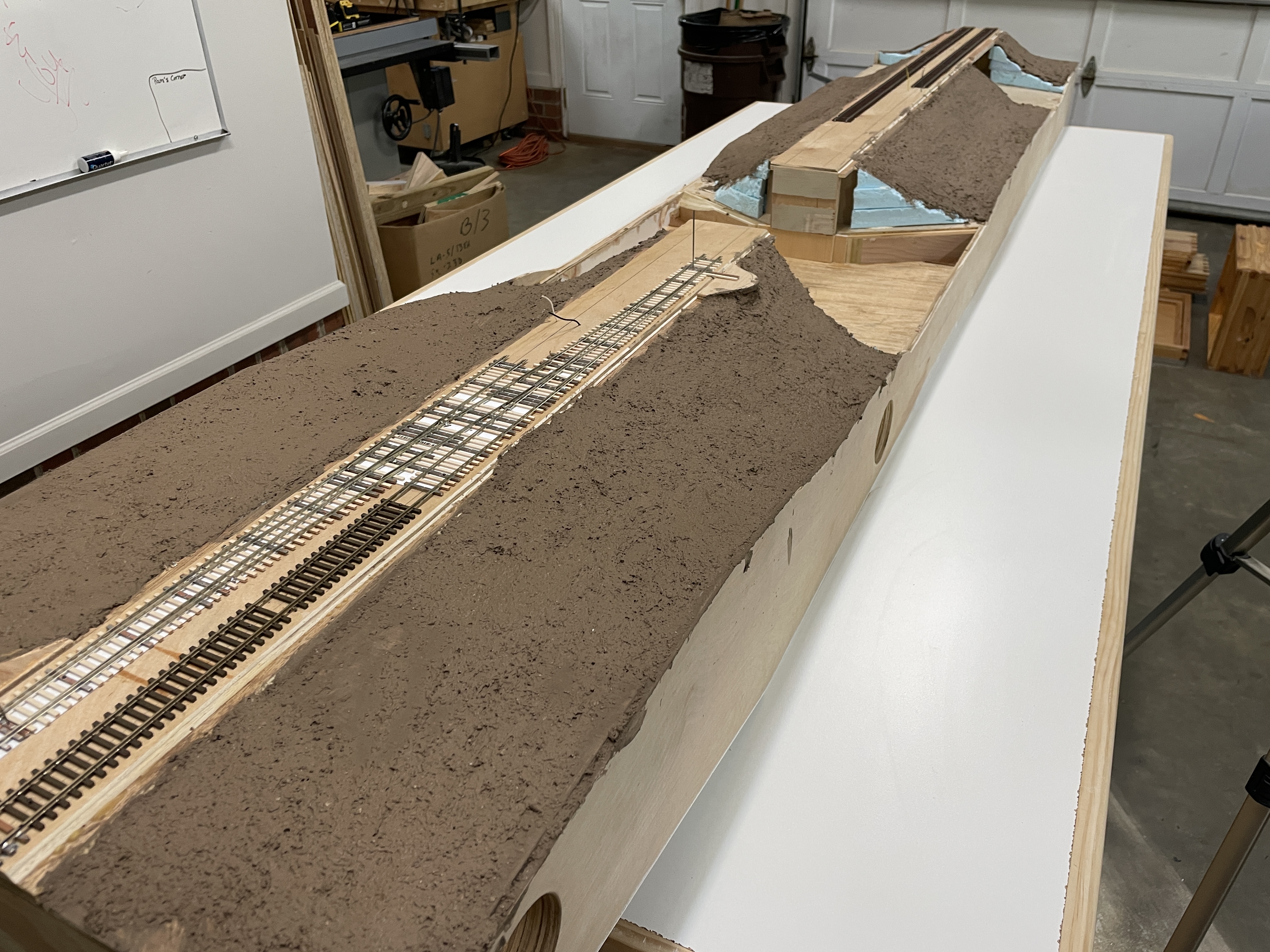
Thread Creek and S. Grand Traverse Street will be the first module section for Flint. It is a high-side half whale belly module box featuring a 3-inch raised fill. The 8-foot section will include a #10 right hand crossover, a bridge over Thread Creek, and a second bridge over S. Grand Traverse St. The section will have a standard template frontier on the east end and terminate with the track elevated on the fill at a proprietary front on the west end thus requiring at least one more section to make it a true module.
 |
| East end in the foreground |

 |
| Pocket cut for installing and servicing Blue Point switch machines |
 |
| #10 crossover on east end |
By increasing the gauge of piano wire to .054, I was able to drop the Blue Point down using a 2-inch standoff mount. This allows the mechanism linkage to be engaged much easier from below the deck.
 |
| 2-inch standoff mount |

 |
| The switch machine's throwbar can be easily reach from below the deck |
For this project I will be creating my own bridges over Thread Creek and S. Grand Traverse St. using components from two Walthers 70ft single track deck girder bridge kits, both PC board and wooden ties, and scratchbuilt abutments.
 |
| PC board bridge ties |
 |
| S. Grand Traverse St. concrete deck girder bridge |
 |
| Thread Creek open deck girder bridge |

I began work on the abutment during a cold spell in North Carolina. The garage was too cold to work and heating it every day was just not practical. Abutments however could be worked on indoors.
I started by cutting a flat sheet of .060 styrene to the basic dimensions required for this particular set of abutments. I then drew the locations of all essential elements and started building out from there.


After adding more column depth to the backside, I then sanded the front and sides smooth.


I then build the wing walls using the same process of stacking. The wing walls can be built flat and do not require built-in batter. They will be angled, offset, tilted and glued in place to match up with the batter of the abutments.

Once all the wing walls were complete, I started to work on the surface detail. The two southern wing walls bear the brunt of the water damage as Thread Creek flows south to north in this location. The southeast wing wall and eastern abutment both sustain direct impact of flood water damage. I believe it is for this reason that the railroad decided to put in a dam under the bridge in an effort to deflect and redirect water flow in order to mitigate this occurrence.

The southern wing walls have been resurfaced at some point, perhaps more than once. The resurface material has cracked along most of the original underlying concrete. For these cracks, I first drew straight lines with a pencil and ruler, and then hand traced the path with my Exacto knife. I also outlined the areas that would be spalled using the Dremel tool.


For the two abutments and both of the north wing walls, I glued strips of HO scale 1x6, .010x.060, and scale 1x12 to the face to replicate the pour lines created by the concrete forms.


I then sanded them to mostly smooth, leaving a very thin shadow of the board pattern. This came out very close to the look I was going for. I wanted to present a random pattern. I think that the painting and weathering process will get me to the final look I am trying to achieve.
I then created the surface detail for the southeast wing and repeated the process previously discussed.

It was then sanded, test fitted and glued to the abutment. Like before, corresponding surface detail was added to the abutment face. Then the remaining wing walls were glued on.
Here are the final products ready for primer paint and then weathering.
 |
| East abutment |
 |
| West abutment |
Back at the module section, the abutments were then test fitted into the gap to make sure the final dimensions were as I intended them to be. This also gave me the opportunity to determine the final height of the tray I would be creating in order to work on the creek detail away from the project. In the photo you can see the rough sketch of the creek as well as the styrene I will be using to represent the damn. The foam has also been formed and contoured using the same techniques previously discussed in other sections of the blog. At this point the module section was ready for the first application of Ground Goop.

The first layer of Ground Goop was applied, and I kept it about an inch from both of the gaps. This was to ensure that I could have more control when I go to the point of seating the abutments for both bridges.
Once the first layer had hardened up sufficiently, I placed Goop behind each abutment and used cling wrap (you can use anything you have available) to protect the abutments as I press fitted them into the location they would eventually be mounted in.


The next layer of scenery is the sanded grout. I use a variety of colors and brand names, but I primarily stick to Polyblend. Some sanded grouts have different additives and thus different water absorption qualities than others. Polyblend seems to wick well with wet water. Regardless of the self-adhesive claims the companies advertise, I always use additional glue. For my base layer of sanded grout, I start by putting down a layer of white glue. I then use a spoon do sprinkle my various colors of grout in the desired locations. Next, I give them a thorough spray of wet water followed by a wet project brush in which I swirl and mix in the grout with the underlying glue. I keep everything very wet which also assists in blending colors into one another. Keep in mind past railroad practices of using old cinder as a fill and sub-roadbed material. I favor the color "Haystack" for general soil, but this will vary for each modeler to match the geographic area being represented. The result is what is seen in the pics below. At this point it will just need a few days to dry.


While the grout was drying, I turned my attention back to the bridges. A slight adjustment in my original plan required me to move bridge ties. Rather than spend time doing this, I chose to make new bridge track sections and save these old ones for the next bridge project. The pic below shows the spacer jig I use for soldering PC bridge ties in place. The styrene blocks labeled "Top" set the dimensions for the inside portion of the bridges on double track mainline.

I also created a jig to solder stanchions onto PC ties to support the handrailing.

The new bridge tracks were then test fitted into place to make sure everything was correct.


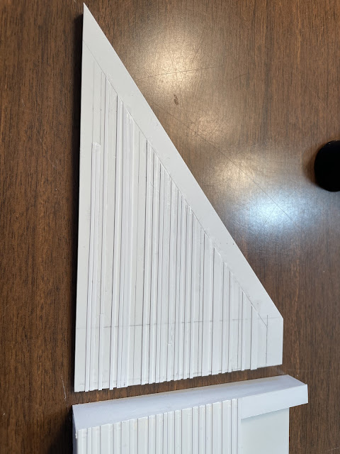
Full profile 3/64 x 3/64 basswood bridge ties were then glued into place. Gaps were left in the westbound track for the walkway and handrail stanchion ties.


Turning next to the S. Grand Traverse Street bridge, I started by creating a profile template for the cantilever concrete deck supports. At first, I was going to design and 3D print these, but I opted to scratch build instead because the bridge was a one-off and I only needed 16. I researched the prototype bridges in order to confirm my decision. About halfway thru the project, I realized I had not looked at the I-75 bridge between Bristol and Torrey Yards further west. CRAP!!! There will be about 32 more needed for that bridge so they may yet be designed.
 |
| Paper template to view the design. |
 |
| I used .030 styrene for the web, and HO scale 2x6 for the flanges. |
 |
| The white strip of styrene filler is where the concrete deck will sit. |
 |
| Test fitting the components. |

Once I was satisfied with the look, I started creating the stanchions for the walkway. There are two different size handrails on this bridge. The top rail is 4" pipe. The bottom rail is 3" pipe. I created another jig for aligning and drilling the holes. Once drilling was complete, I glued the stanchions in place.
 |
| Base flanges glued in place along edge of walkway. |
 |
| Stanchions glued in place. |
 |
| Checking hole alignment for rails. |
 |
| Second row of stanchions. |

 |
| Rails glued in place. |
S. Grand Traverse Street was the next project. I started with measuring out the lanes, curbs, sidewalks, etc... From there I began to build up from the .060 styrene base. Most of the time I use scale 6" material for curbs and sidewalks however at this location the curb height is much lower...perhaps less than 3" in some areas. I opted to use .040 material to represent these. At this location, the sidewalks are also dropping downgrade going under the bridge and not following the same elevation of the road. I just used pieces of my scrap styrene to build up the necessary areas. It will all be covered with scenery material in the end anyway.

 |
| Getting a look at lane width. The crown will not be as pronounced once the road is glued in place. |
After I was satisfied with the dimensional aspects, I started drawing and scribing the cracks and holes in the road surface. I use the back of an Exacto blade for road cracks, and a Dremel Tool for concrete spawling and potholes.

When I was happy with the degree of deterioration, I sanded the entire surface using a circular motion in order to avoid lines.
Back to the Thread Creek trestles, I created a jig/reference tool to assist in alignment / positioning of the milling machine when drilling handrail holes in the stanchions.

Once the stanchions were all drilled, I began glueing them in place. I used a straight edge to ensure alignment. It was then test fitted into the abutments.


For the handrails I used Clover House #247 Rod and Pipe .023 diameter brass wire. This measures out to around an HO scale 2" which matched the prototype.

With the handrails in place, I did a final test fit and then cut the extended ties for all four approaches. In the photos I could see that the last 4 crossties on each approach got progressively wider with the last one being full width of the bridge. In addition, there is a full width tie that sits on the top of the concrete abutment. Once these were cut, I finished painting the track.


 |
| Remaining ties for bridge approaches as well as gap fillers for the rest of the module section. |
 |
| For the base coat of paint for the track in this area of Flint I chose Rust-oleum Khaki as the primer followed by a light coat of GAF Shingle Match Barkwood. |
 |
| Primer coat. |
 |
| GAF Barkwood. |
Next, I took some time and created my 3D switch throw knobs and got them installed. This crossover is a control point and will eventually get Tortoise switch machines installed for dispatcher control. I don't have my control boxes designed yet so I wanted to get them operational for immediate use.
 |
| New switch throw knobs minus LED lighting |
The rest of the track was then painted and received wash applications as per my SOP for track.
 |
Once my cinder base had dried, I began applying the ballast layers using my custom mixes for the GTW Mainline. The sub-roadbed layer depicts older ballast which is darker in appearance as can be seen here in the image below. The top layer being the newest is also the lightest in color.
Finally, it was time to start adding green stuff. I started by determining where the edges of my grass lines and wood lines would be. From there I began applying the first layer of dead grass. For this I use a custom mix of 2mm static grass. Once the first layer has had time to dry, I vacuum up the loose grass from the first layer and then put a second layer of 2mm dead grass down which is slightly different in color. This is a very subtle difference, but it is very noticeable. I then apply layers of green 4-6mm, then Savanah grass clusters, then dead grass clusters. Further examples of this process can be seen in more detail on the Owosso section of the Grand Rapids sub in its own tab at the top of the Home Page.
Next was the forest floor areas starting with the bottom layers of composting material. This is followed by fallen sticks and branches. Then the larger fallen logs covered with moss, more layers of fallen leaves, a sprinkling of medium ground foam representing the leavy forest floor vegetation, and finally a final layer of dried leaves.
Moving my attention back to Thread Creek, I then glued the dam in place using a board and weights to make sure that everything stayed straight and flat. This is a new technique I am experimenting with for the creek bed. The entire thing is removeable so I can work on the details away from the module. Once done I will set it in place and profile the fascia edges to match the creek. After all the cutting is done I will glue it in place and doctor up the transition. I still need to create a test pour mockup as I did with the Shiawassee River pour to look at color selections and more importantly, multi-height pours. This scene will feature four different water heights. The beaver dam backs up the creek causing it to flow over the dam. From behind the dam the water drops again to the area below the beaver dam. It then drops slightly a third time over a small secondary debris dam downstream from the beaver dam. This should be a fun project.
 |
| Ground Goop in place forming the base of the creek banks. |
While the creek bed was drying, I started with the base colors for S Grand Traverse Street and the concrete deck bridge over the street. For the street itself I started with a solid coat of Rust oleum Primer Gray. I then did my misting pattern with Satin Stone Gray and ...will add later... . Once I was satisfied that I had achieved the appropriate look based on time period photos of the prototype, I set it aside to dry. After it had dried, I taped off the curb and sidewalk areas and gave them a solid coat of Satin Stone Gray. Once dry, I went over the sidewalks and curbs with an airbrush of Tamiya XF-55 Deck Tan.
 |
| A look at the road in place prior to painting the bridge. |
For the base primer coat for the concrete deck bridge, I used Tamiya XF- ...... I then spray painted the abutments and wing walls with the same Satin Stone Gray as the sidewalks, followed by an airbrush of Tamiya XF-55 Deck Tan.

I also applied the Tamiya Deck Tan to the concrete walkways on the top of the bridge. For the bridge girders and walkway supports I used Tamiya XF-16 Flat Aluminum.

I masked off the street for painting the pavement markings. I started by marking the street centerline as well as lane centers. Using DOT standards and photos of the area I then masked makings as appropriate. I went over everything with white first to include the center double line. After that dried for about an hour, I went back over the center double line with yellow.
 |
| Masked for painting |
 |
| Base colors complete and ready for further weathering |
Next up I masked off the stanchions and handrails for the bridge and painted them the same Aluminum color as the bridge girders.
 |
| A final look with all base colors applied |
 |
| NOTE: Not seen here, I have backings for the abutment pockets painted in the same colors. |
I had originally left room for the control point signals when I spaced everything out, but I had forgot to put the mounting pads in when I did the initial roadbed. I went back and glued these in place. These areas are supported on the side of the fill with steel piling retaining walls which I have designed for 3D printing.
Base colors were also applied to the Thread Creek bridge. I used Tamiya XF-1 Flat Black for the bridge girders. For the abutments I once again started with Valspar Hunters White the same as I had used with the Shiawassee River bridge in Bancroft.
 |
| Base colors applied to girders, abutments, and wing walls |
With the base colors applied, it was now time to move to the abutment weathering. For this I use a multi-layering process which is time consuming, but the end result makes it well worth the time and effort. As I list the steps below, note that each layer is sealed with Dull Cote or equivalent.
 |
| Base coat. Valspar Hunter White or equivalent desired base color. |
 |
| Step 1: Aim White powder followed immediately with Bragdon Ash powder |
 |
| Step 2: Bragdon Dust Bowl Brown |
 |
| Step 3: Bragdon Grimy Gray |
 |
| Step 4: Bragdon Ash |
 |
| Step 5: Wash using acrylic craft paints (3pts-White, 2pts-Sand, 1 pt Quaker Gray) |
The wash layers lock in the colors beneath and serve as a new base for the second series of powder layers.
 |
| Step 6: Doc O'Brian Grungy Gray |
 |
| Step 7: Bragdon Dust Bowl Brown |
 |
| Step 8: Bragdon Ash |
 |
| Step 9: Doc O'Brian Highlight White |
 |
| Step 10: AIM White |
 |
| Step 11: Doc O'Brian Grungy Gray |
 |
| Step 12: Wash Two, same as first using acrylic craft paints (3pts-White, 2pts-Sand, 1 pt Quaker Gray) |
 |
| Step 13: Bragdon Dust Bowl Brown followed by Doc O'Brian Highlight White |
 |
| Step 14: Bragdon Dust Bowl Brown |
Now that the powders have all been sealed in place, I turn to acrylic layering of the wing walls which show a significant amount of spalling and deterioration due to time and water damage. I use the same acrylic colors as the washes above; however, these are applied using a smaller brush and are painted on heavier to depict desired placement according to the prototype photos. Once again, acrylic craft paint colors used are White, Sand, and Quaker Gray.
 |
| First layer of acrylics |
 |
| Second layer with more emphasis on lighter colors |
 |
| Third layer is a light wash of sand and gray to blend everything together |
Once the acrylic layers were in place, I sealed everything in preparation for the dark wash layer which highlights and enhances the surface detail.
 |
| Post dark wash layer |
After the dark wash layer, I turned to colored pencils to depict some of the finer details.
 |
| Colored pencils used to add finer details including cracks and fishers and other features as noted on the prototype |
 |
| A look at the model outdoors in natural light. |
Saginaw St and Flint Station
I-475
Michigan Lumber Company, located along Clifford Street just east of the old Flint station and I-475, had two spur tracks entering through a gate on the east end of the facility.
 |
| 2015, LOOKING EAST at Michigan Lumber Co with I-475 along the bottom of photo |


Dort Highway:
The Dort Highway bridge has an interesting art deco design...
Flint Mass Transportation Authority (MTA):
C&O Crossing:
Just east of Flint Amtrak, the GTW crosses the Chessie (now CSX) double track main.
 |
| C&O CROSSING looking west from Court Street |
ZONE V:
Belsay Yard:
This was one of the original yards in Flint which served the automotive industry.


ZONE C:
AC Spark Plug:

 |
| Looking west |
 |
| Looking east |
 |
| AC SPARK PLUG viewed from Robert T Longway Blvd |
ZONE D:


 |
| C&O crossing just west of AC Spark Plug |
James Lumber:
Just to the west of AC Spark Plug, immediately after the crossing of the double track C&O is James Lumber. This is a simple industry that consists of a single spur track for the spotting of forest products cars near the storage facility.
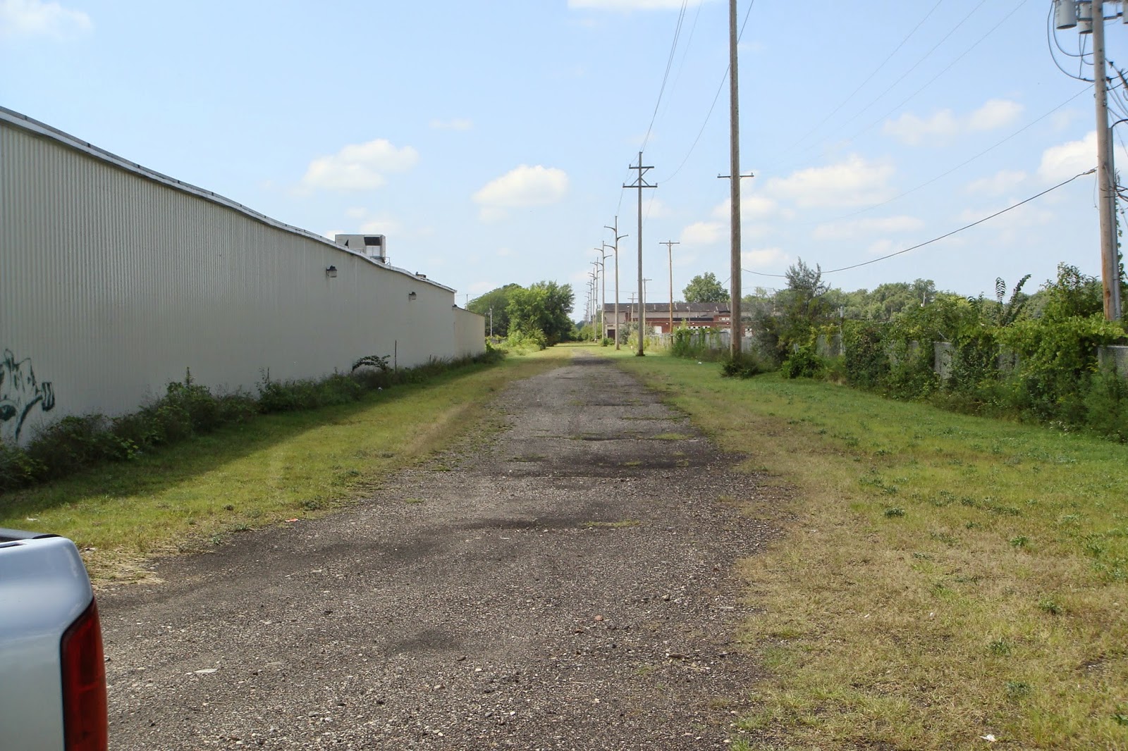 |
| Old road bed along the north side of James Lumber |
 | |
| JAMES LUMBER viewed from Robert T Longway Blvd on south side. |
MODELING FLINT:
BRISTOL YARD TOWER:
I was able to get a copy of the elevation blueprints from the GTW Historical Society for the Bristol Yard Tower. Since I knew I would be building this structure full scale, I bypassed the cardboard mockup and moved ahead with the styrene core of the building.
BRISTOL CAR REPAIR SHOP:
The Car Repair Shop, located in the service facility area at the east end of Bristol Yard is a sizable structure. The main building, which was added in the early 1970's, is 70 feet wide and 220 feet long. The inner work area consists of two tracks each with 11 different 20-foot work bays (total of 22 work bays). This large steel structure is attached to the side of the old pre-existing repair shop building that is located along the south side.
Jeff I plan on modeling GTW Flint in 65. I would love to contact you to see if you know where I can find some more info.
ReplyDeleteDustin, My apologies for not responding sooner. I just now saw this comment post. I have updated my profile to show my email contact information. Would sure like the opportunity to exchange notes and/or ideas.
ReplyDeleteAny updates on the layout, specifically the Flint portions? I want to thank you for this website, it's been a wealth of info as I plan my plywood paradise. I'm at a loss how to compress Happy Valley/Chevy in the Hole to fit in my room and am dying to get any info from anywhere on how to tackle it. I grew up in the Mott Park area in the 70's and 80's so it holds a pretty dear place in my heart
ReplyDeleteHello Thomas. Unfortunately, no updates to the Flint area. Whenever I get something new, I will post it. Chevy Manufacturing Div. is quite a large plant, although model railroad wise, you can compress it a great deal. The large plant sizes could be adjusted for your space, and/or backdrop buildings could be utilized. What kind of space are you working with?
DeleteI have been working on Chevy in the Hole for a Free-mo module. I attended Kettering, sadly right when all the buildings were being torn down, but the photos and aerials I have found show it was alot more active even in the 90's. I'd be happy to share what I have if it would help you. drisdon@gmail.com
DeleteThanks for the reply - roughly around the walls in the shape of a "C" 6ft X 22ft X8ft with the chance of a good peninsula of 6ft width. Selective compression will be a huge factor - if I can get the iconic Chevrolet sign and overpass between Factories 2 and 2a and some of the on site switching to get the feel of the place I'd be super happy. Maybe I should switch to N scale! :)
ReplyDeleteThanks again for your wonderful site!